SSI
|
| ERP2U Power Supply Design Guide, V1.0 | |
| Asset Tag | {Not used, code is zero length byte} |
|
|
|
|
|
| FRU File ID | {Not required} | |
|
|
|
|
| PAD Bytes | {Added as necessary to allow for 8 | |
|
|
|
|
8.3.3.2MultiRecord Area
As defined by the IPMI FRU document. The following record types shall be used on this power supply:
∙Power Supply Information (Record Type 0x00)
∙DC Output (Record Type 0x01)
∙No other record types are required for the power supply.
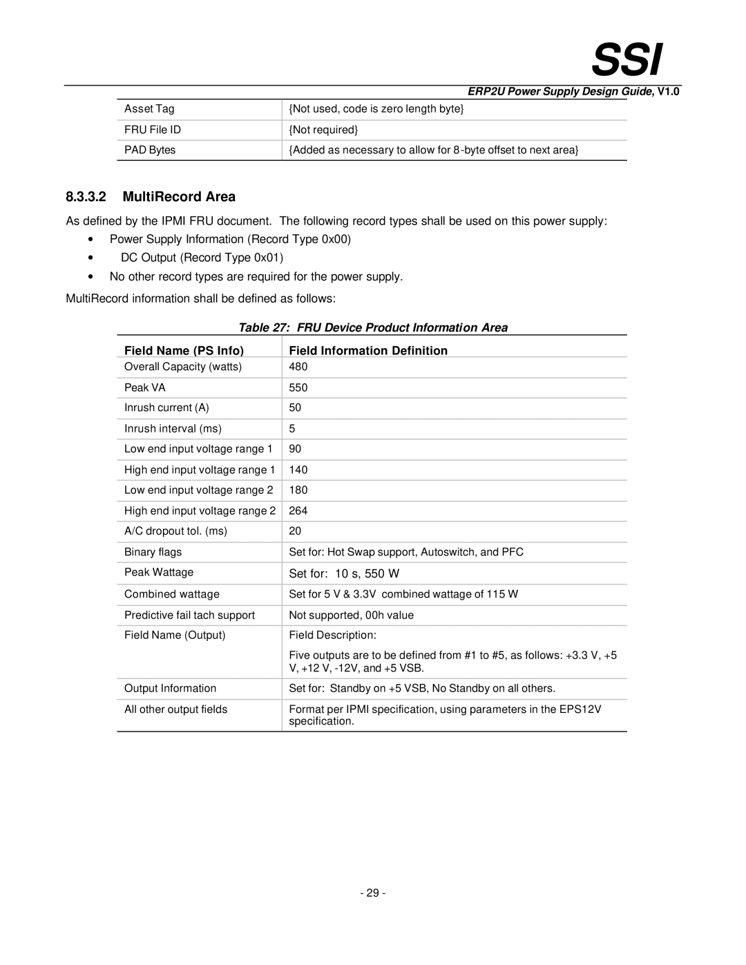
MultiRecord information shall be defined as follows:
Table 27: FRU Device Product Information Area
Field Name (PS Info) | Field Information Definition |
Overall Capacity (watts) | 480 |
|
|
Peak VA | 550 |
|
|
Inrush current (A) | 50 |
|
|
Inrush interval (ms) | 5 |
|
|
Low end input voltage range 1 | 90 |
|
|
High end input voltage range 1 | 140 |
|
|
Low end input voltage range 2 | 180 |
|
|
High end input voltage range 2 | 264 |
|
|
A/C dropout tol. (ms) | 20 |
|
|
Binary flags | Set for: Hot Swap support, Autoswitch, and PFC |
|
|
Peak Wattage | Set for: 10 s, 550 W |
|
|
Combined wattage | Set for 5 V & 3.3V combined wattage of 115 W |
|
|
Predictive fail tach support | Not supported, 00h value |
|
|
Field Name (Output) | Field Description: |
| Five outputs are to be defined from #1 to #5, as follows: +3.3 V, +5 |
| V, +12 V, |
|
|
Output Information | Set for: Standby on +5 VSB, No Standby on all others. |
|
|
All other output fields | Format per IPMI specification, using parameters in the EPS12V |
| specification. |
|
|
- 29 -
