Manuals
/
Intel
/
Computer Equipment
/
Computer Hardware
Intel
I945P
specifications
System Block Diagram
Models:
I945P
1
11
70
70
Download
70 pages
2.25 Kb
8
9
10
11
12
13
14
15
Specifications
Install
System Block Diagram
Password
Defaults Menu
Supported Configuration
To enter the Setup Program
Advanced Bios Features
Voltage Adjust Menu
Chipest Serial ATA Setting
Page 11
Image 11
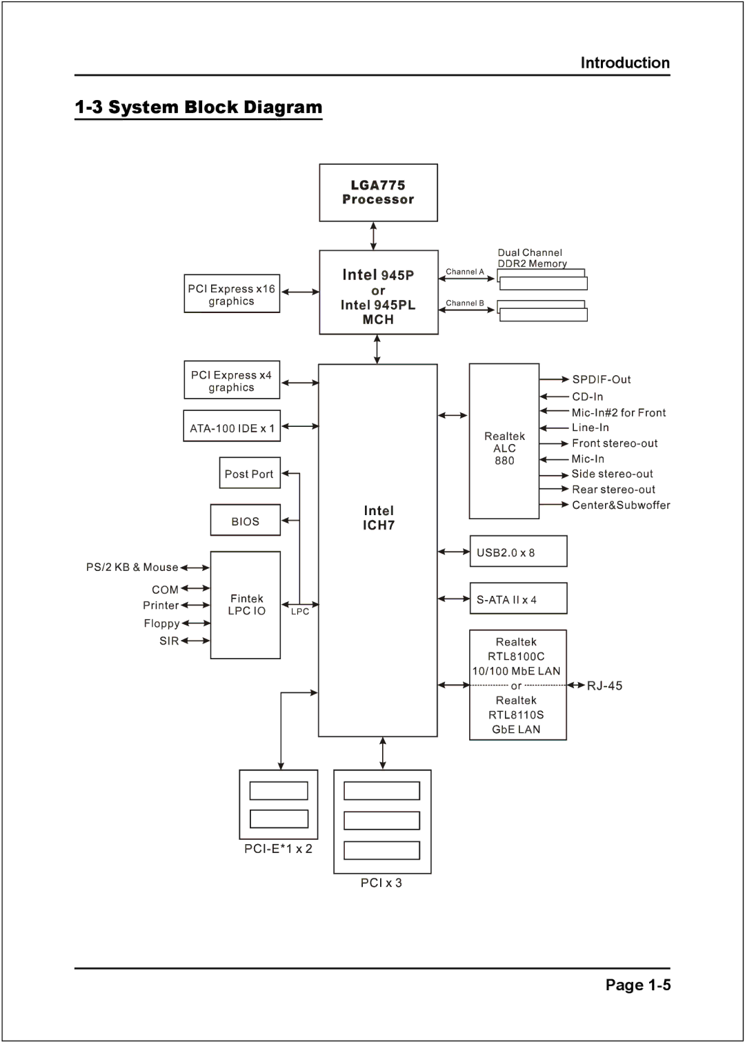
Introduction
1-3
System Block Diagram
Page
1-5
Page 10
Page 12
Page 11
Image 11
Page 10
Page 12
Contents
Manual Revision October 25
Disclaimer of Warranties
Post Port Frequently Asked Questions
Table of Contents
Section Driver Installation
Left Blank
Introduction
Mainboard Features
Ultra ATA100
Special Features Bios Features Magic Health
System Block Diagram
Introduction
Main Memory
Specification
Mainboard Specification Processor
Chipset
Audio
IDE
Front Panel Controller
Onboard connector and pin-header
Peripheral Interfaces
At Rear Panel
Supported Operating System
Specification Special Features
Form Factor
Mainboard Layout
Installation
CPU Installation
Installation Easy Installation Procedure
Step
Settings Normal Default Clear Cmos
Installation Jumper Settings
Supported Configuration
Dual Channel interface
Installation System Memory Configuration
Memory Installation
Memory configurations supported
Installation VGA Card Installation
PCI-E VGA Card
Jcpufan / Jpwrfan / Jsysfan
Installation Device Connectors
PW1
GND
CUSB3 CUSB4
CFP CIR Cspk
Installation Thermo Stick Function Optional
Installation Acpi S3 Suspend To RAM Function
Installation Acpi S3 Suspend To RAM Function
Installation
Main Menu
To enter the Setup Program
Standard Cmos Setup
Standard Cmos Setup
Bios Features Setup
Advanced Bios Features
Hyper-Threading Technology
Chipset Features Setup
Advanced Chipset Features
Dram Timing Selectable
PCI Express Function
Integrated Peripherals
Chipset IDE Devices
Chipest Serial ATA Setting
Legacy Devices
Parallel Port Mode
Power Management
Power Management Setup
PCI-E device PME function Options Enabled, Disabled
Wake-Up by PCI Card
PCI Express related items
PNP/PCI/PCI-E Configuration
PC Health Status
Interrupt requests are shared as shown below
Displays the current system/CPU temperature
Smart Fan example
PowerBOIS Features
Power Bios Features
CPU CLOCK/SPEED
Voltage Adjust Menu
Load Optimized Defaults
Defaults Menu
Load Fail-Safe Defaults
Supervisor/User Password Setting
Enter Password
Exit Without Saving
Exiting Bios
Save & Exit Setup
Save to Cmos and Exit Y/N? Y
Easy Driver Installation
Drivers Installation
Sound Effect
Drivers Installation Realtek Sound Manager Quick User-guide
Above shows the phone jack setup for 8 channel mode
Drivers Installation Speaker Configuration
Spdif
Drivers Installation General
Audio Wizard
Drivers Installation Audio Wizard
Drivers Installation
Appendix
Flashing the Bios
Key in File Name to save previous Bios to file
Appendix B
Appendix
Appendix
If password is set, ask for password
Top
Page
Image
Contents