Mechanical Requirements
3.5Package/Socket Stackup Height
Table
Table 3-1. Intel® Xeon® 5000 Sequence Package and Socket Stackup Height
Processor | Integrated Stackup Height 1 (mm) | |
From Top of Board to Top of IHS | ||
| ||
|
| |
7.628 - 8.120 | ||
|
| |
7.693 - 8.155 | ||
|
| |
7.604 - 8.124 | ||
|
|
Notes:
1.Preliminary Guidance. This data is provided for information only, and should be derived from: (a) the height of the socket seating plane above the motherboard after reflow, given in the LGA771 Socket Mechanical Design Guide with its tolerances; (b) the height of the package, from the package seating plane to the top of the IHS, and accounting for its nominal variation and tolerances that are given in the corresponding processor datasheet.
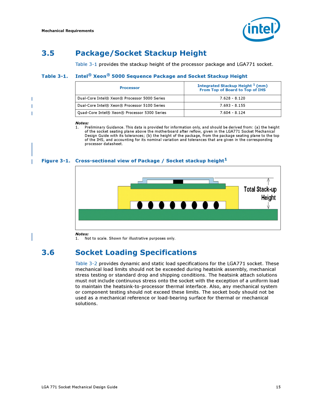
Figure 3-1. Cross-sectional view of Package / Socket stackup height1
Notes:
1. Not to scale. Shown for illustrative purposes only.
3.6Socket Loading Specifications
Table
LGA 771 Socket Mechanical Design Guide | 15 |