Mechanical Requirements
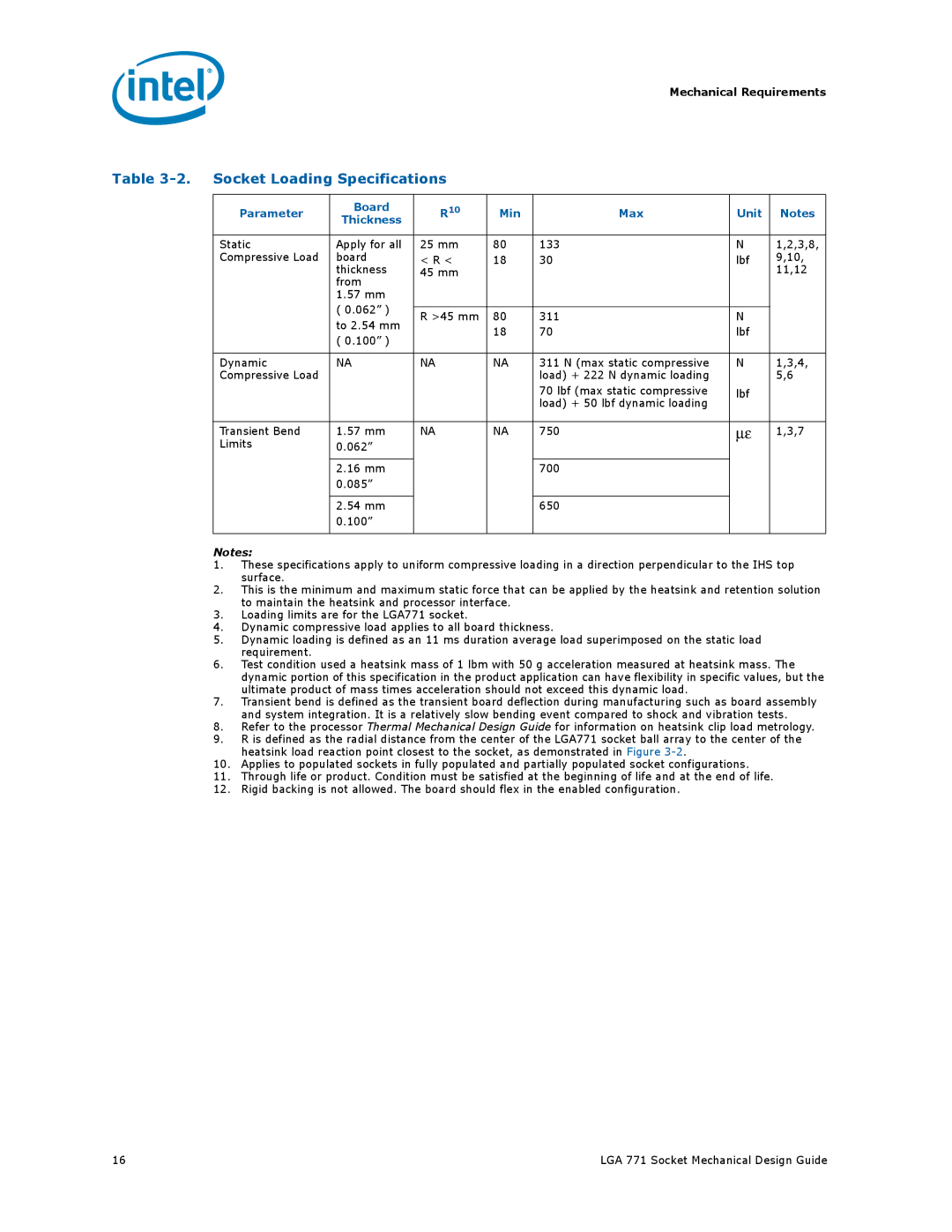
Table 3-2. Socket Loading Specifications
Parameter | Board | R10 | Min | Max | Unit | Notes |
| Thickness |
|
|
|
|
|
|
|
|
|
|
|
|
Static | Apply for all | 25 mm | 80 | 133 | N | 1,2,3,8, |
Compressive Load | board | < R < | 18 | 30 | lbf | 9,10, |
| thickness | 45 mm |
|
|
| 11,12 |
| from |
|
|
|
|
|
| 1.57 mm |
|
|
|
|
|
| ( 0.062” ) |
|
|
|
|
|
| R >45 mm | 80 | 311 | N |
| |
| to 2.54 mm |
| ||||
|
| 18 | 70 | lbf |
| |
| ( 0.100” ) |
|
| |||
|
|
|
|
|
| |
|
|
|
|
|
|
|
Dynamic | NA | NA | NA | 311 N (max static compressive | N | 1,3,4, |
Compressive Load |
|
|
| load) + 222 N dynamic loading |
| 5,6 |
|
|
|
| 70 lbf (max static compressive | lbf |
|
|
|
|
| load) + 50 lbf dynamic loading |
|
|
|
|
|
|
|
|
|
Transient Bend | 1.57 mm | NA | NA | 750 | με | 1,3,7 |
Limits | 0.062” |
|
|
|
|
|
|
|
|
|
|
|
|
| 2.16 mm |
|
| 700 |
|
|
| 0.085” |
|
|
|
|
|
|
|
|
|
|
|
|
| 2.54 mm |
|
| 650 |
|
|
| 0.100” |
|
|
|
|
|
|
|
|
|
|
|
|
Notes:
1.These specifications apply to uniform compressive loading in a direction perpendicular to the IHS top surface.
2.This is the minimum and maximum static force that can be applied by the heatsink and retention solution to maintain the heatsink and processor interface.
3.Loading limits are for the LGA771 socket.
4.Dynamic compressive load applies to all board thickness.
5.Dynamic loading is defined as an 11 ms duration average load superimposed on the static load requirement.
6.Test condition used a heatsink mass of 1 lbm with 50 g acceleration measured at heatsink mass. The dynamic portion of this specification in the product application can have flexibility in specific values, but the ultimate product of mass times acceleration should not exceed this dynamic load.
7.Transient bend is defined as the transient board deflection during manufacturing such as board assembly and system integration. It is a relatively slow bending event compared to shock and vibration tests.
8.Refer to the processor Thermal Mechanical Design Guide for information on heatsink clip load metrology.
9.R is defined as the radial distance from the center of the LGA771 socket ball array to the center of the heatsink load reaction point closest to the socket, as demonstrated in Figure
10.Applies to populated sockets in fully populated and partially populated socket configurations.
11.Through life or product. Condition must be satisfied at the beginning of life and at the end of life.
12.Rigid backing is not allowed. The board should flex in the enabled configuration.
16 | LGA 771 Socket Mechanical Design Guide |