Intel order number D31979-007
Revision
Intel Server Board S5000PAL / S5000XAL TPSRevision History
Iii
Date Revision Modifications Number
Disclaimers Intel Server Board S5000PAL / S5000XAL TPS
Disclaimers
Table of Contents
Light Guided Diagnostics
Jumper Block Settings
Power and Environmental Specifications
105
101
108
111
Viii Revision Intel order number D31979-007
List of Figures Intel Server Board S5000PAL / S5000XAL TPS
Intel Server Board S5000PAL / S5000XAL TPS List of Tables
List of Tables
List of Tables Intel Server Board S5000PAL / S5000XAL TPS
Page
Server Board Use Disclaimer
Chapter Outline
Introduction Intel Server Board S5000PAL / S5000XAL TPS
12Revision Intel order number D31979-007
Feature Description
Intel Server Board S5000PAL / S5000XAL Feature Set
Intel Server Board S5000PAL / S5000XAL TPS Product Overview
Product Overview Intel Server Board S5000PAL / S5000XAL TPS
Server Board Layout
14Revision Intel order number D31979-007
Connector and Component Locations
Sata
LDM
Light Guided Diagnostic LED Locations
External I/O Connector Locations
Server Board Mechanical Drawings
40.39
PCI BKT Drop Down
TP02294
10.16 16.51 113.13 199.21 285.75 182.83 274.32 298.51
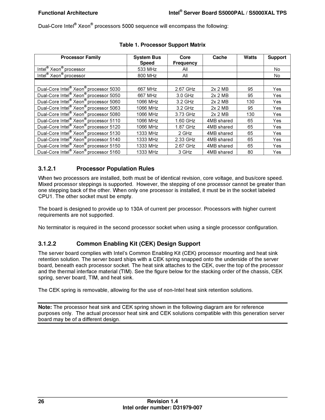
Functional Architecture
System Bus Interface
Intel 5000P and 5000X Memory Controller Hubs MCH
Processor Support
Common Enabling Kit CEK Design Support
Processor Population Rules
Processor Support Matrix
26Revision Intel order number D31979-007
CEK Processor Mounting
Memory Sub-system
Supported Memory
Memory Rasum Featuresi
Minimum Non-Mirrored Mode Configuration
Dimm Population Rules and Supported Dimm Configurations
Branch Channel B Channel a
Recommended Four Dimm Configuration
Non-mirrored mode memory upgrades
32Revision Intel order number D31979-007
Single Branch Mode Sparing Dimm Configuration
Snoop Filter 5000X MCH only
ESB-2 IO Controller
1.1 PCI32 32-bit, 33-MHz PCI Bus Segment
PCI Sub-system
PXA 64-bit, 133MHz PCI-X* Bus Segment
1.3 PE1 One x4 PCI Express* Bus Segment
1.6 PE6, PE7 Two x4 PCI Express* Bus Segments
1.5 PE4, PE5 Two x4 PCI Express* Bus Segments
PCI Riser Slots
Intel Embedded Server RAID Technology II Support
Serial ATA Support
36Revision Intel order number D31979-007
Parallel ATA Pata Support
Video Support
USB 2.0 Support
Intel Embedded Server RAID Technology Option ROM
Video Memory Interface
Video Modes
Dual Video
Video Modes
Intel I/O Acceleration Technology
Network Interface Controller NIC
MAC Address Definition
NIC2 Status LED
Super I/O
Pin Signal Name Serial Port a Header Pin-out
Serial Ports
Serial a Header Pin-out
RJ45 Signal Abbreviation
Pins What happens at system reset…
Floppy Disk Controller
Keyboard and Mouse Support
System Health Support
Wake-up Control
42Revision Intel order number D31979-007
Platform Management
Board Connector Matrix
Board Connector Information
44Revision Intel order number D31979-007
Power Connector Pin-out J3K3
Power Connectors
Power Connector Pin-out J3K4
Power Supply Signal Connector Pin-out J1K1
Intel RMM Connector Pin-out J1C5
Intel Remote Management Module RMM Connector
Pin Signal Name
System Management Headers
Pin Intel RMM NIC Module Connector Pin-out J1B2
Intel RMM NIC Connector
3 LCP/AUX Ipmb Header
Riser Card Slots
Ipmb Header
Pin Side a PCI Spec Signal
Pin Side B PCI Spec Signal
Pin-Side B PCI Spec Signal Pin-Side a PCI Spec Signal
Full-height Riser Slot Pin-out J4F1
50Revision Intel order number D31979-007
Pin-Side B PCI Spec Signal Pin-Side a
PAR64
52Revision Intel order number D31979-007
Bridge Board Connector
SSI Control Panel Connector
Front Panel SSI Standard 24-pin Connector Pin-out J3H2
Pin Bridgeboard Connector Pin-out J4G1
54Revision Intel order number D31979-007
VGA Connector
I/O Connector Pin-out Definition
NIC Connectors
VGA Connector Pin-out J6A1
Intel I/O Expansion Module Connector
IDE Connector
Pin IDE Connector Pin-out J3G1
56Revision Intel order number D31979-007
Sata Connector Pin-out J1H1, J1G2, J1G1, J1F2, J1E3
Sata Connectors
Keyboard and Mouse Connector
Serial Port Connectors
External USB Connector Pin-out J5A1, J6A2
USB 2.0 Connectors
Internal USB Connector Pin-out J1J1
Pin Signal Name Type Description
SSI Fan Connector Pin-out J9K1,J5K1,J3K1,J3K2,J7A2,J7A1
Fan Headers
60Revision Intel order number D31979-007
Recovery Jumpers J1D1, J1D2, J1D3
Recovery Jumper Blocks
Jumper Name Pins What happens at system reset…
BMC Force Update Procedure
Cmos Clear and Password Reset Usage Procedure
62Revision Intel order number D31979-007
Bios Select Jumper J3H1
Bios Select Jumper
External RJ45 Serial Port Jumper Block
5-Volt Standby LED
Light Guided Diagnostics
66Revision Intel order number D31979-007
System ID LED and System Status LED
Color State Criticality Description
System Status LED BMC Initialization
Processor Fault LED
Dimm Fault LEDs
Post Code Diagnostic LEDs
70Revision Intel order number D31979-007
Server Board Design Specifications
Processor Power Support
Server Board Power Requirements
TDP Power Max Tcase Icc MAX 130 W 70º C 150 a
Load Ratings
Turn On No Load Operation
No load operating range
72Revision Intel order number D31979-007
Standby Outputs
Grounding
Remote Sense
Voltage Regulation
Dynamic Loading
Common Mode Noise
Capacitive Loading
Closed-Loop Stability
Soft Starting
Ripple / Noise
Timing Requirements
Ripple and Noise
Out 10% V out
MIN MAX Units
78Revision Intel order number D31979-007
Residual Voltage Immunity in Standby Mode
Australia / New Zealand AS/NZS 3548 Emissions
Product Safety & Electromagnetic EMC Compliance
Reference Example
FCC Verification Statement USA
Electromagnetic Compatibility Notices
ICES-003 Canada
Europe CE Declaration of Conformity
RRL Korea
Bsmi Taiwan
English translation of the notice above
Product Ecology Compliance
Japan Recycling
Other Markings
Compliance Compliance Reference Description Marking Example
84Revision Intel order number D31979-007
Appendix a Integration and Usage Tips
ƒ Sensor Type
ƒ Assertion / De-assertion Enables
ƒ Event / Reading Type
ƒ Event Offset/Triggers
ƒ Criticality
ƒ Default Hysteresis
ƒ Standby
86Revision Intel order number D31979-007
Value Bility Type
NMI
STB
Revision
Revision Intel order number D31979-007
Revision
Acpi
Bios EPS
PCIe Link1
Revision
Dimm A2
Dimm D2
ECC
B01 Dimm
100 Revision Intel order number D31979-007
LEDs Red Green
Post Progress Code LED Example
102Revision Intel order number D31979-007
Revision 103 Intel order number D31979-007
Pre-EFI Initialization Module Peim / Recovery
Runtime Phase / EFI Operating System Boot
104Revision Intel order number D31979-007
Error Code Error Message Response
Post Error Messages and Handling
Revision Intel order number D31979-007 105
ROM
106Revision Intel order number D31979-007
Post Error Beep Codes
Post Error Beep Codes
BMC Beep Codes
Revision 107 Intel order number D31979-007
Appendix E Supported Intel Server Chassis
Page
Slim-Line Optical Drive Bay
Revision 111 Intel order number D31979-007
Intel Server Board S5000PAL / S5000XAL TPS Glossary
Term Definition
112Revision Intel order number D31979-007
Glossary Intel Server Board S5000PAL / S5000XAL TPS
Revision 113 Intel order number D31979-007
114Revision Intel order number D31979-007
Reference Documents