S875WP1-E specifications
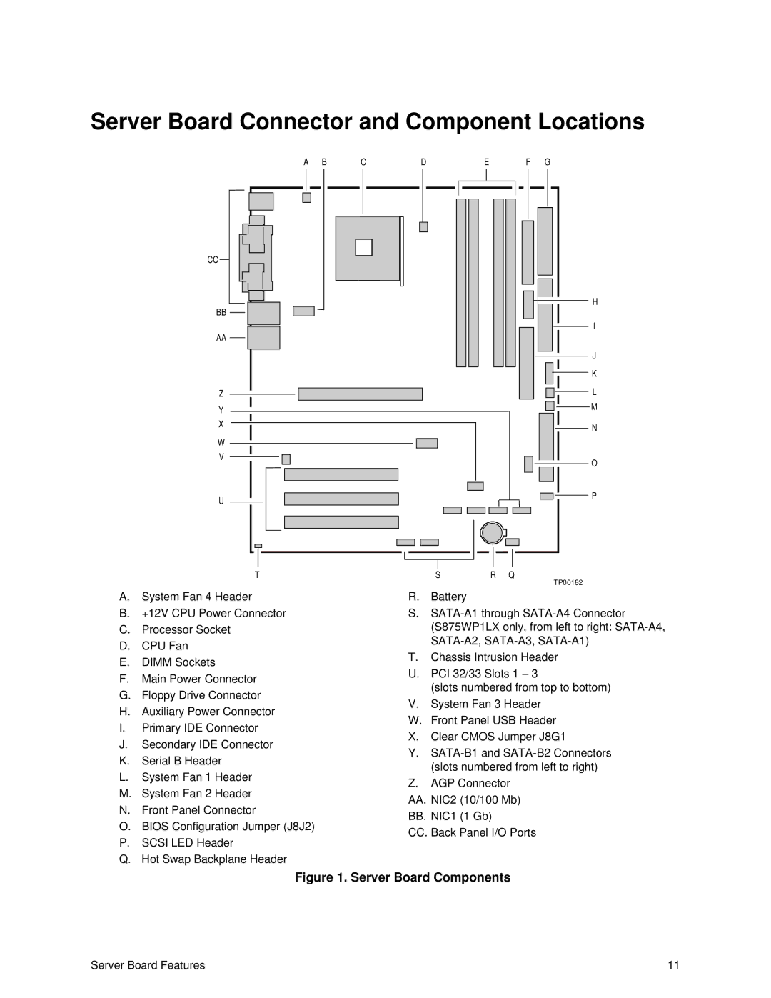
The Intel S875WP1-E is a high-performance server motherboard designed to meet the demanding requirements of enterprise-level applications. It is ideally suited for those seeking a robust solution for data centers, cloud computing, and various business applications. Built on the Intel 875P chipset, the S875WP1-E delivers impressive features and technologies that enhance functionality and reliability.One of the standout characteristics of the Intel S875WP1-E is its support for dual Intel Xeon processors. This allows for significant processing power, enabling businesses to run multiple applications simultaneously without compromising performance. With its dual-socket configuration, the motherboard supports a range of Xeon processors, maximizing scalability for evolving workloads.
The motherboard supports up to 16GB of DDR SDRAM, utilizing ECC (Error-Correcting Code) memory, which ensures data integrity and system stability. The capability to handle large amounts of memory is critical for applications requiring high data throughput and reliability, such as virtualization and database management.
In terms of storage, the S875WP1-E features several Serial ATA (SATA) ports, supporting RAID configurations, which can enhance data redundancy and performance. This flexibility in storage options ensures that businesses can tailor their systems according to specific storage needs. Additionally, it also supports PATA (Parallel ATA) drives, allowing for integration of legacy systems.
The expansion capabilities of the S875WP1-E are notable, as it includes multiple PCI Express and PCI slots, accommodating various expansion cards, including graphics cards, network interfaces, and storage controllers. This versatility is essential for organizations looking to customize their systems based on specific application requirements.
Networking capability is another highlight of the Intel S875WP1-E. It comes equipped with integrated Gigabit Ethernet, providing fast network access essential for server operations. The motherboard also features additional options for network expansion, ensuring that businesses can connect seamlessly to their networks.
Thermal management is another strong aspect of the S875WP1-E design. With a range of features aimed at maintaining optimal operating temperatures, including robust power regulation, it helps to prolong the lifespan of components and enhance overall system reliability.
In summary, the Intel S875WP1-E motherboard is a powerful solution for enterprise environments, offering dual processor support, ample memory capacity, flexible storage options, and comprehensive networking capabilities. Its design prioritizes stability and performance, making it an ideal choice for those looking to build a reliable server infrastructure tailored to their organization's needs.

