Intel Server Board SE7221BK1-E
Date Revision Modifications Number
SE7221BK1-ETechnical Product Specification
Revision
SE7221BK1-E Technical Product Specification
Disclaimers
Table of contents
Connectors
Configuration Jumpers
Bios Setup Utility
Acpi Implementation
SE7221BK1 -E Technical Product Specification
Boot Block Post Progress Codes Power Information
Absolute Maximum Ratings
Hardware Monitoring
Industry Canada ICES-003
Glossary
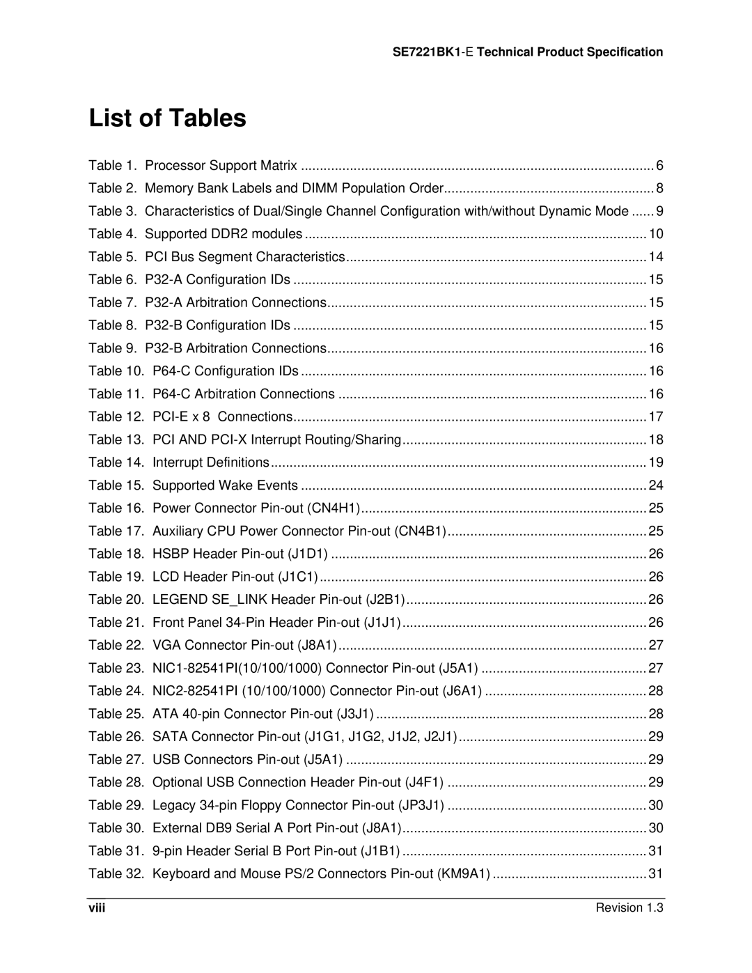
List of Tables
Viii
SE7221BK1-E Technical Product Specification
Revision
List of Figures
Page
Introduction
SE7221BK1-E Feature Set
Server Board Overview
ƒ USB
ƒ LPC Low Pin Count bus segment with one embedded devices
CPU
PCI-X 100 Slot
Functional Architecture
Processor Subsystem
Memory Subsystem
Interrupts and Apic
Memory Dimm Support
Processor Support Matrix
Memory Configuration
Location Dimm Label Channel Population Order
Memory Bank Label Definition
Throughput Level Configuration Characteristics
Intel E7221 Chipset
1.1 DDR2 Configurations
Gmch Memory Architecture Overview
Graphics Memory Controller Hub Gmch
Supported DDR2 modules
3 ICH6R
PCI Bus P32-A I/O Subsystem
Power Management
PCI Express* X4 Subsystem
PCI Bus Master IDE Interface
USB Interface
Super I/O
Serial Ports
Bios Flash
O Subsystem
PCI Subsystem
System Health Support
2.2 P32-B Arbitration
2 P32-B 66-MHz PCI-X Subsystem SE7221BK1LX sku only
1.2 P32-A Arbitration
P64-C Configuration IDs
3 P64-C 66/100-MHz PCI-X Subsystem
3.2 P64-C Arbitration
P32-B Arbitration Connections
NIC Connector and Status LEDs
Video Controller
Network Interface Controller NIC
PCI-E
Interrupt Routing
Legacy Interrupt Routing
Apic Interrupt Routing
Legacy Interrupt Sources
ISA Interrupt Description
PCI Error Handling
Serialized IRQ Support
Gmch Intr CPU
ICH6
ICH6 Ioapic DMI Interface
Super I/O
PCI Interface
PA IRQ8 Interface
PB IRQ8 Interface
Acpi
Front Panel Switches
Acpi Implementation
Power Button On to Off Legacy Power Button On to Off Acpi
Wake up Sources Acpi and Legacy
Supported Wake Events
USB
Connectors
Main Power Connector
Power Connector Pin-out CN4H1
Auxiliary CPU Power Connector Pin-out CN4B1
Front Panel Connector
I2C Header
Hsbp Header Pin-out J1D1
LCD Header Pin-out J1C1
VGA Connector
NIC Connector
VGA Connector Pin-out J8A1
NIC1-82541PI10/100/1000 Connector Pin-out J5A1
IDE Connector
NIC2-82541PI 10/100/1000 Connector Pin-out J6A1
ATA 40-pin Connector Pin-out J3J1
IDEA1 Diag IDEA0 IDEA2 IDEDCS0# IDEDCS1# IDEHDACT# GND
Sata Connector
USB Connector
Sata Connector Pin-out J1G1, J1G2, J1J2, J2J1
USB Connectors Pin-out J5A1
Floppy Connector
Serial Port Connector
Legacy 34-pin Floppy Connector Pin-out JP3J1
External DB9 Serial a Port Pin-out J8A1
Keyboard and Mouse Connector
Keyboard and Mouse PS/2 Connectors Pin-out KM9A1
Miscellaneous Headers
Fan Header
Intrusion Cable Connector
Intrusion Cable Connector J1A1Pin-Out Pin Signal Name
HDD LED Header J1E1 Pin-Out Pin Signal Name
HDD LED Header
Configuration Jumpers
System Recovery and Update Jumpers
Rolling Bios selection header
System Recovery and Update Jumper Options
Bios Setup Utility
Configuration Reset
Keyboard Commands
Localization
Load Setup Defaults?
Cancel
ESC
Post
Entering Bios Setup
Bios Setup, Main Menu Options
Save configuration changes and exit setup?
Feature Options Help Text Description
Processor configuration sub-menu
Bios Setup, Advanced Menu Options
Bios Setup, Processor configuration sub-menu options
Advanced menu
IDE configuration sub-menu
Bios Setup IDE Configuration Menu Options
Enabled
Compatible
Bios Setup, IDE Device Configuration Sub-menu Selections
Host & Device
Auto
Cdrom Armd
Floppy configuration sub-menu
Super I/O configuration sub-menu
Bios Setup, Floppy Configuration Sub-menu Selections
Bios Setup, Super I/O Configuration Sub-menu
USB configuration sub-menu
Bios Setup, USB Configuration Sub-menu Selections
PCI configuration sub-menu
Bios Setup, PCI Configuration Sub-menu Selections
FDD
Cdrom
Boot menu
Memory configuration sub-menu
Bios Setup, Memory Configuration Sub-menu Selections
Bios Setup, Boot Menu Selections
Boot settings configuration sub-menu selections
Boot device priority sub-menu selections
Bios Setup, Boot Settings Configuration Sub-menu Selections
Bios Setup, Boot Device Priority Sub-menu Selections
North Bridge Chipset Configuration
Bios Setup, Removable Drives Sub-menu Selections
Bios Setup, Atapi Cdrom Drives Sub-menu Selections
Chipset Menu
South Bridge Chipset Configuration
Enabled, 8MB
Feature Options Help Text
Dram Clocks
Security menu
PXH Bridge Configuration
Bios Setup, Security Menu Options
Minute
Bios Setup, Server Menu Selections
Server menu
Bios Setup, System Management Sub-menu Selections
System management sub-menu selections
Stays Off
Stay On
Serial Console features sub-menu selections
Event Log configuration sub-menu selections
Bios Setup Serial Console Features Sub-menu Selections
Bios Setup, Event Log Configuration Sub-menu Selections
Upgrading the Bios
Preparing for the Upgrade
Recording the Current Bios Settings
Bios Setup, Exit Menu Selections
Obtaining the Upgrade Utility Creating a Bootable Diskette
Flash Update Utility
Flash Architecture and Flash Update Utility
Rolling Bios and On-line updates
Recovery Mode
Bios Recovery
Multi-Disk Recovery
\split AMIBOOT.ROM Amiboot
Manually Recovering the Bios
Summary of Beep codes
Error Handling and Reporting
Post Error Beep Codes
Post Error Beep Codes
Beeps Error Message Post Progress Code Description
Bios Event Log
Post Error Messages and Handling
Error Code Error Message Response
Pmmmemallocerr
Post Progress Codes and Messages
Post Code Checkpoints
Post Code Checkpoints
Languagemoduleerr
Enable IRQ-0 in PIC for system timer interrupt
Initializes remaining option ROMs
Boot Block Initialization Code Checkpoints
Bootblock Initialization Code Checkpoints
Boot Block Recovery Code Checkpoints
Bootblock Recovery Code Checkpoints
DIM Code Checkpoints
Acpi Runtime Checkpoints
DIM Code Checkpoints
Acpi Runtime Checkpoints
Diagnostic LEDs
Diagnostic LED Post Progress Codes
Boot Block Post Progress Codes
Post Progress Code LED Example
Post Progress Codes
SE7221BK1-ETechnical Product Specification
SE7221BK1-E Technical Product Specification
Power Information
Intel Server Board SE7221BK1-E Power Budget
Board Power Budget
Power Supply Rail Voltages Units Watts
Power Supply Specifications
Power Timing Requirements
Board Power Supply Voltage Specification
5VSB output voltage rise time shall be from 1.0ms to 25.0ms
Output Voltage Timing Turn On/Off Timing
+5VSB
Dynamic Loading
Transient Load Requirements
AC Line Transient Specification
AC Line Fast Transient EFT Specification
Absolute Maximum Ratings
AC Line Sag Transient Performance
Hardware Monitoring
Mean Time Between Failures Mtbf Test Results
Monitored Components
Monitored Components
HTHEMPDA/C
Temperature
FANIN7 PIN #9
Fan Speed Control Block Diagram
Fan Speed Control
Product Safety Compliance
Product Regulatory Compliance
Chassis Intrusion
Product EMC Compliance
Electromagnetic Compatibility Notices
FCC USA
Korean RRL Compliance
Europe CE Declaration of Conformity
Taiwan Declaration of Conformity
Replacing the Back-Up Battery
Australia / New Zealand
Mechanical Specifications
Product Code Calculated Mtbf Operating Temperature
Calculated Mean Time Between Failures Mtbf
Mtbf Data
SE7221BK1-E Server Board Mechanical Drawing
Sku 1 Pedestal mount I/O shield mechanical drawing Revision
Sku 2 Pedestal mount I/O shield mechanical drawing
Page
Glossary SE7221BK1-E Technical Product Specification
Term Definition
LPC
MBE
MSB
Mtbf
SE7221BK1-E Technical Product Specification Glossary
VGA
VID
ZCR