SECTION
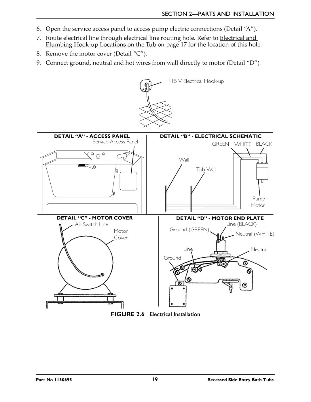
6.Open the service access panel to access pump electric connections (Detail “A”).
7.Route electrical line through electrical line routing hole. Refer to Electrical and Plumbing Hook‐up Locations on the Tub on page 17 for the location of this hole.
8.Remove the motor cover (Detail “C”).
9.Connect ground, neutral and hot wires from wall directly to motor (Detail “D”).
115 V Electrical
DETAIL “A” - ACCESS PANEL | DETAIL “B” - ELECTRICAL SCHEMATIC | |
Service Access Panel | GREEN | WHITE BLACK |
| ||
| Wall |
|
| Tub Wall |
|
|
| Pump |
|
| Motor |
DETAIL “C” - MOTOR COVER
Air Switch Line
Motor
Cover
DETAIL “D” - MOTOR END PLATE
Ground (GREEN) | Line (BLACK) | |
Neutral (WHITE) | ||
| ||
Line | Neutral | |
Ground |
|
FIGURE 2.6 Electrical Installation
Part No 1150695 | 19 | Recessed Side Entry Bath Tubs |