SECTION
13. Model 3750 Only ‐ Perform the following steps to install the shower wand:
A. Determine the mounting location for the shower wand and mark this on the wall.
NOTE: A shower wand, shower hose, supply elbows, hanger pegs and a flexible supply line have been supplied with the tub.
B.Plumb the supply line to the diverted output port of the mix valve.
C.Route the supply line behind the back wall to the location of your choice.
D.Drill a hole in the wall to accommodate the plastic compression fitting on the back and the chrome elbow on the front.
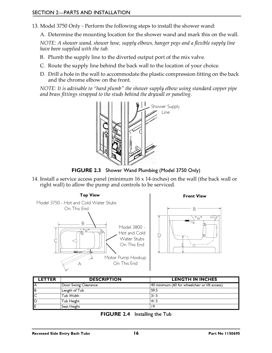
NOTE: It is advisable to “hard plumb” the shower supply elbow using standard copper pipe and brass fittings strapped to the studs behind the drywall or paneling.
Shower Supply
Line
FIGURE 2.3 Shower Wand Plumbing (Model 3750 Only)
14.Install a service access panel (minimum 16 x 14‐inches) on the wall (the back wall or right wall) to allow the pump and controls to be serviced.
Top View
Model 3750 - Hot and Cold Water Stubs
On This End
| B | Model 3800 - |
|
| |
|
| Hot and Cold |
C |
| Water Stubs |
| On This End | |
|
| |
|
| Motor Pump Hookup |
A |
| On This End |
D
Front View
B |
E |
LETTER | DESCRIPTION | LENGTH IN INCHES |
A | Door Swing Clearance | 40 minimum (60 for wheelchair or lift access) |
B | Length of Tub | 59.5 |
C | Tub Width | 31.5 |
D | Tub Height | 41.5 |
E | Seat Height | 19 |
FIGURE 2.4 Installing the Tub
Recessed Side Entry Bath Tubs | 16 | Part No 1150695 |