the center locking screw with an Allen wrench (see figure 12).
4.Position the bearing by turning the bushing. Set the clearance at approximately 0.001 inch. (The blade should be in a vertical position between the bearings. (See figure 13.)
5.Tighten the center locking screw with anAllen wrench while holding the eccentric bushing in position with the
6.Use the same procedure to adjust the other guide bearing.
7.When the adjustment is correct, the guide bear- ings should rotate freely with slight pressure of the finger (with the blade stopped).
8.Adjust
Test Cutting to Verify
Adjustment Accuracy
Test cuts can be used to determine whether or not you have adjusted the blade accurately. Use
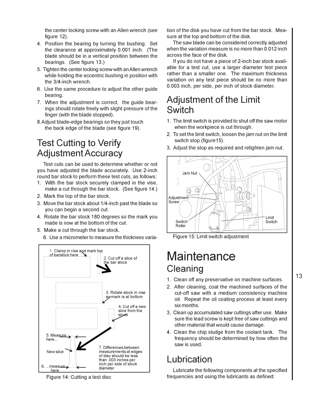
1.With the bar stock securely clamped in the vise, make a cut through the bar stock. (See figure 14.)
2.Mark the top of the bar stock.
3.Move the bar stock about
4.Rotate the bar stock 180 degrees so the mark you made is now at the bottom of the cut.
5.Make a cut through the bar stock.
6.Use a micrometer to measure the thickness varia-
1. Clamp in vise and mark top of barstock here ![]()
2. Cut off a slice of the bar stock
3. Rotate stock in vise so mark is at bottom
4. Cut off a new slice from the stock
tion of the disk you have cut from the bar stock. Mea- sure at the top and bottom of the disk.
The saw blade can be considered correctly adjusted when the variation measure is no more than 0.012 inch across the face of the disk.
If you do not have a piece of
Adjustment of the Limit Switch
1.The limit switch is provided to shut off the saw motor when the workpiece is cut through.
2.To set the limit switch, loosen the jam nut on the limit switch stop (figure15).
3.Adjust the stop as required and retighten jam nut.
Jam Nut |
|
Adjustment |
|
Screw |
|
Switch | Limit |
Switch | |
Roller |
|
Figure 15: Limit switch adjustment
Maintenance
Cleaning
1. | Clean off any preservative on machine surfaces. |
2. | After cleaning, coat the machined surfaces of the |
| |
| oil. Repeat the oil coating process at least every |
| six months. |
3. | Clean up accumulated saw cuttings after use. Make |
| sure the lead screw is kept free of saw cuttings and |
| other material that would cause damage. |
4. | Clean the chip sludge from the coolant tank. The |
13
5.Measure ![]() here...
here... ![]()
New slice ![]()
![]()
6. ...measure ![]()
here
7.Differences between measurements at edges of disc should be less than .003 inches per inch per side of stock diameter
frequency should be determined by how often the |
saw is used. |
Lubrication
Lubricate the following components at the specified
