Coolant Flow
CAUTION: THE COOLANT PUMP MUST BE SUB- MERGED BEFORE OPERATING TO PREVENT DAM- AGE TO THE PUMP.
1.The blade guides are fitted with coolant fittings. Coolant is provided to the fittings through intercon- necting tubing. The coolant is dispensed directly onto the saw blade.
2.Adjust the coolant flow valves on the top, rear of the saw head as required to provide the desired flow. The flow should be no more than the blade can draw into the workpiece by blade movement.
3.The coolant flow can be stopped in two ways:
1)By using the coolant pump switch on the electrical equipment box, or
2)By closing the coolant flow valves on the top,
rear of the saw head.
Coolant Mixture and Quantity
The general purpose coolant is a mixture of water soluble oil and water. Mix one part of soluble oil (TRIM SOL) to ten parts of water (one quart oil, ten quarts of water). Eleven quarts of coolant are required for the coolant pump to operate properly.
There are numerous coolants on the market that are formulated for special applications. Consult your local distributor for details in the event you have a long range production task, or are required to cut some of the more exotic materials.
Adjustments
The efficient operation of the
If a new blade does not restore the machine’s cut- ting accuracy and quality, refer to the Troubleshooting section (or the blade manufacturer’s guide) for condi- tions to consider and adjustments that can be made to increase the life of the blade.
To change the blade, refer to Changing Blades in the Maintenance section. To adjust the blade tracking, refer to the following procedures.
Blade Tracking Adjustment
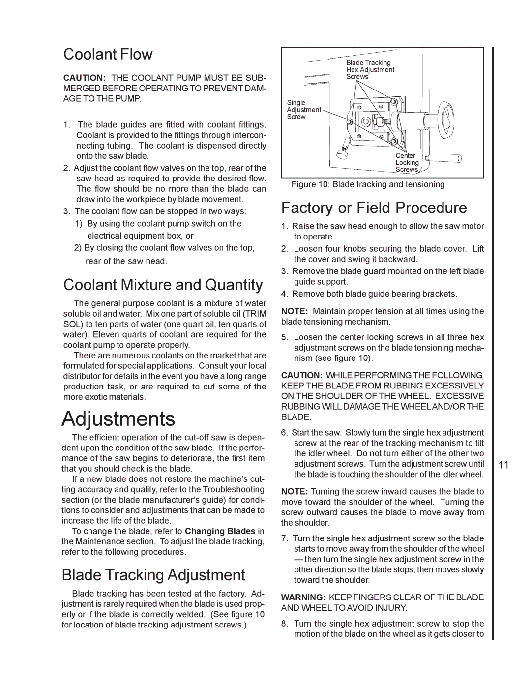
Blade tracking has been tested at the factory. Ad- justment is rarely required when the blade is used prop- erly or if the blade is correctly welded. (See figure 10 for location of blade tracking adjustment screws.)
Blade Tracking
Hex Adjustment
Screws
Single
Adjustment
Screw
Center
Locking
Screws
Figure 10: Blade tracking and tensioning
Factory or Field Procedure
1.Raise the saw head enough to allow the saw motor to operate.
2.Loosen four knobs securing the blade cover. Lift the cover and swing it backward.
3.Remove the blade guard mounted on the left blade guide support.
4.Remove both blade guide bearing brackets.
NOTE: Maintain proper tension at all times using the blade tensioning mechanism.
5.Loosen the center locking screws in all three hex adjustment screws on the blade tensioning mecha- nism (see figure 10).
CAUTION: WHILE PERFORMING THE FOLLOWING, KEEP THE BLADE FROM RUBBING EXCESSIVELY ON THE SHOULDER OF THE WHEEL. EXCESSIVE RUBBING WILL DAMAGE THE WHEELAND/OR THE BLADE.
6.Start the saw. Slowly turn the single hex adjustment screw at the rear of the tracking mechanism to tilt the idler wheel. Do not turn either of the other two adjustment screws. Turn the adjustment screw until the blade is touching the shoulder of the idler wheel.
NOTE: Turning the screw inward causes the blade to move toward the shoulder of the wheel. Turning the screw outward causes the blade to move away from the shoulder.
7.Turn the single hex adjustment screw so the blade starts to move away from the shoulder of the wheel
— then turn the single hex adjustment screw in the other direction so the blade stops, then moves slowly toward the shoulder.
WARNING: KEEP FINGERS CLEAR OF THE BLADE AND WHEEL TO AVOID INJURY.
8.Turn the single hex adjustment screw to stop the motion of the blade on the wheel as it gets closer to
11
