Introduction
This manual includes the operating and maintenance instructions for the JET
Operating Instructions
Controls
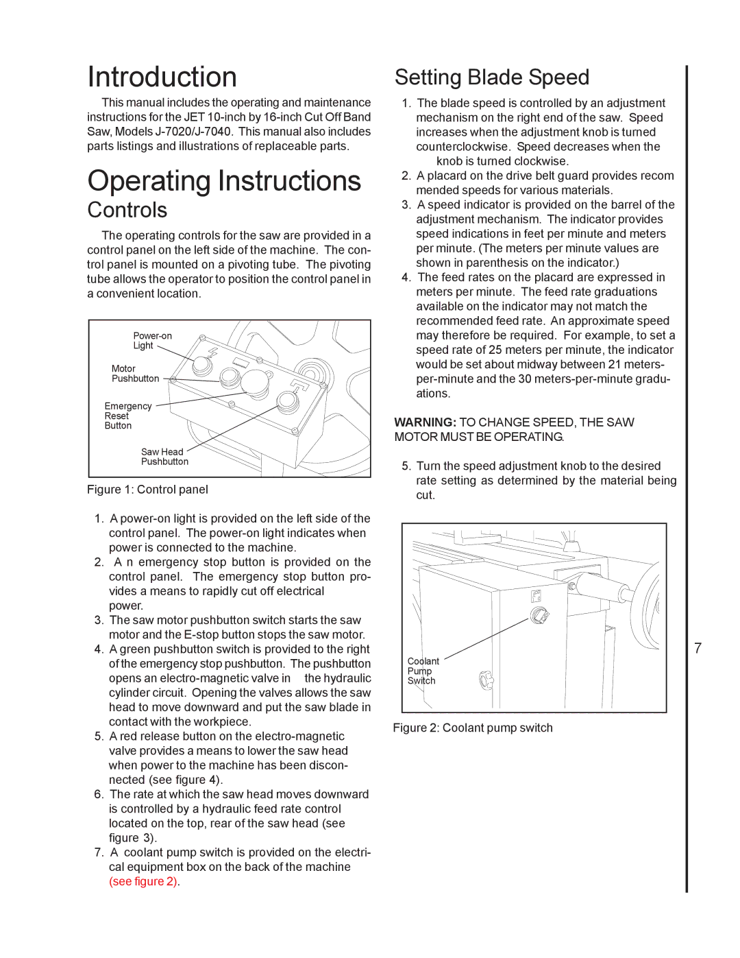
The operating controls for the saw are provided in a control panel on the left side of the machine. The con- trol panel is mounted on a pivoting tube. The pivoting tube allows the operator to position the control panel in a convenient location.
Light |
Motor |
Pushbutton |
Emergency |
Reset |
Button |
Saw Head |
Pushbutton |
Figure 1: Control panel
1.A power-on light is provided on the left side of the control panel. The power-on light indicates when power is connected to the machine.
2.A n emergency stop button is provided on the control panel. The emergency stop button pro- vides a means to rapidly cut off electrical power.
3.The saw motor pushbutton switch starts the saw motor and the
4.A green pushbutton switch is provided to the right of the emergency stop pushbutton. The pushbutton
opens an
5.A red release button on the
6.The rate at which the saw head moves downward is controlled by a hydraulic feed rate control located on the top, rear of the saw head (see figure 3).
7.A coolant pump switch is provided on the electri- cal equipment box on the back of the machine (see figure 2).
Setting Blade Speed
1.The blade speed is controlled by an adjustment mechanism on the right end of the saw. Speed increases when the adjustment knob is turned counterclockwise. Speed decreases when the
knob is turned clockwise.
2.A placard on the drive belt guard provides recom mended speeds for various materials.
3.A speed indicator is provided on the barrel of the adjustment mechanism. The indicator provides speed indications in feet per minute and meters per minute. (The meters per minute values are shown in parenthesis on the indicator.)
4.The feed rates on the placard are expressed in meters per minute. The feed rate graduations available on the indicator may not match the recommended feed rate. An approximate speed may therefore be required. For example, to set a speed rate of 25 meters per minute, the indicator would be set about midway between 21 meters-
WARNING: TO CHANGE SPEED, THE SAW MOTOR MUST BE OPERATING.
5.Turn the speed adjustment knob to the desired rate setting as determined by the material being cut.
7 |
Coolant |
Pump |
Switch |