Angle | Set Workpiece |
Setting | Against Corner |
Block | of Right |
| Vise Jaw |
Left |
|
Vise |
|
Jaw |
|
| Pivot |
Angle | Screw |
Locking |
|
Screw |
|
Figure 6: Adjusting vise
Angle Block |
Locking Handle |
Angle |
Pointer |
Figure 7: Angle setting block
Installation and Adjustment of Work Stop
Figure 5: Securing workpiecThe work stop is used to set up the saw for making multiple cuts of the same length (see figure 8). Install and adjust the work stop as follows:
Stop Post |
Locking Lever |
place it against the work piece.
Starting the Saw
WARNING: NEVER OPERATE THE SAW WITHOUT BLADE COVERS IN PLACE AND SECURED.
CAUTION: MAKE SURE THE BLADE IS NOT IN CON- TACT WITH THE WORKPIECE WHEN THE MOTOR IS STARTED. DO NOT DROP THE SAW HEAD ON THE WORKPIECE OR FORCE THE SAW BLADE THROUGH THE WORKPIECE.
1.Raise the saw head. With the saw motor off, pull the red release button on the
2.Raise the saw head. Push in red release button.
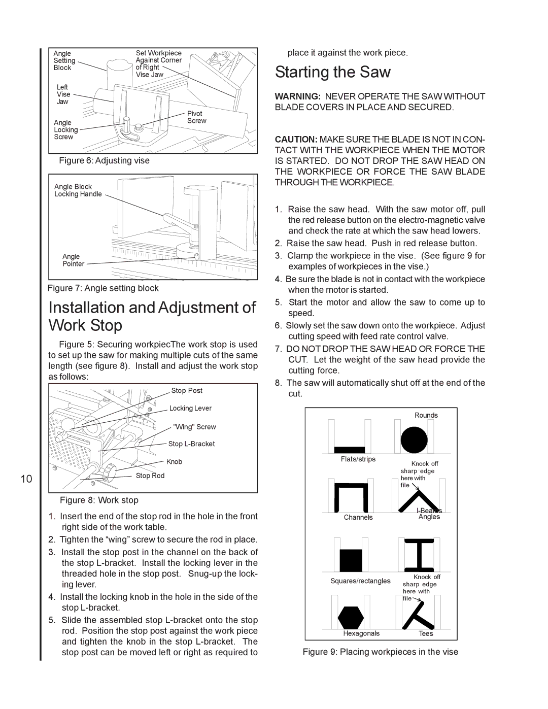
3.Clamp the workpiece in the vise. (See figure 9 for examples of workpieces in the vise.)
4.Be sure the blade is not in contact with the workpiece when the motor is started.
5.Start the motor and allow the saw to come up to speed.
6.Slowly set the saw down onto the workpiece. Adjust cutting speed with feed rate control valve.
7.DO NOT DROP THE SAW HEAD OR FORCE THE CUT. Let the weight of the saw head provide the cutting force.
8.The saw will automatically shut off at the end of the cut.
| "Wing" Screw |
| Stop |
| Knob |
10 | Stop Rod |
|
Figure 8: Work stop
Flats/strips
Rounds
Knock off sharp f fedge here with file ![]()
1. | Insert the end of the stop rod in the hole in the front |
| right side of the work table. |
2. | Tighten the “wing” screw to secure the rod in place. |
3. | Install the stop post in the channel on the back of |
| the stop |
| threaded hole in the stop post. |
| ing lever. |
4. | Install the locking knob in the hole in the side of the |
| stop |
5. | Slide the assembled stop |
| rod. Position the stop post against the work piece |
| and tighten the knob in the stop |
Channels
Squares/rectangles
Hexagonals
Angles
Knock off sharp fedge here with filef ![]()
![]()
Tees
stop post can be moved left or right as required to |