If alignment is required:
3.Move the
4.Slightly loosen the hex nuts (F, G).
5.To move the splitter (E) right or left, adjust all four nuts evenly to move the retaining plate and tab accordingly. To tilt the angle of the splitter to achieve alignment, adjust the two front hex nuts (F) or two rear hex nuts (G) only.
6.When adjustment is complete, tighten the hex nuts (F, G).
7.Check the alignment by repeating steps 1 and 2. If necessary, repeat steps
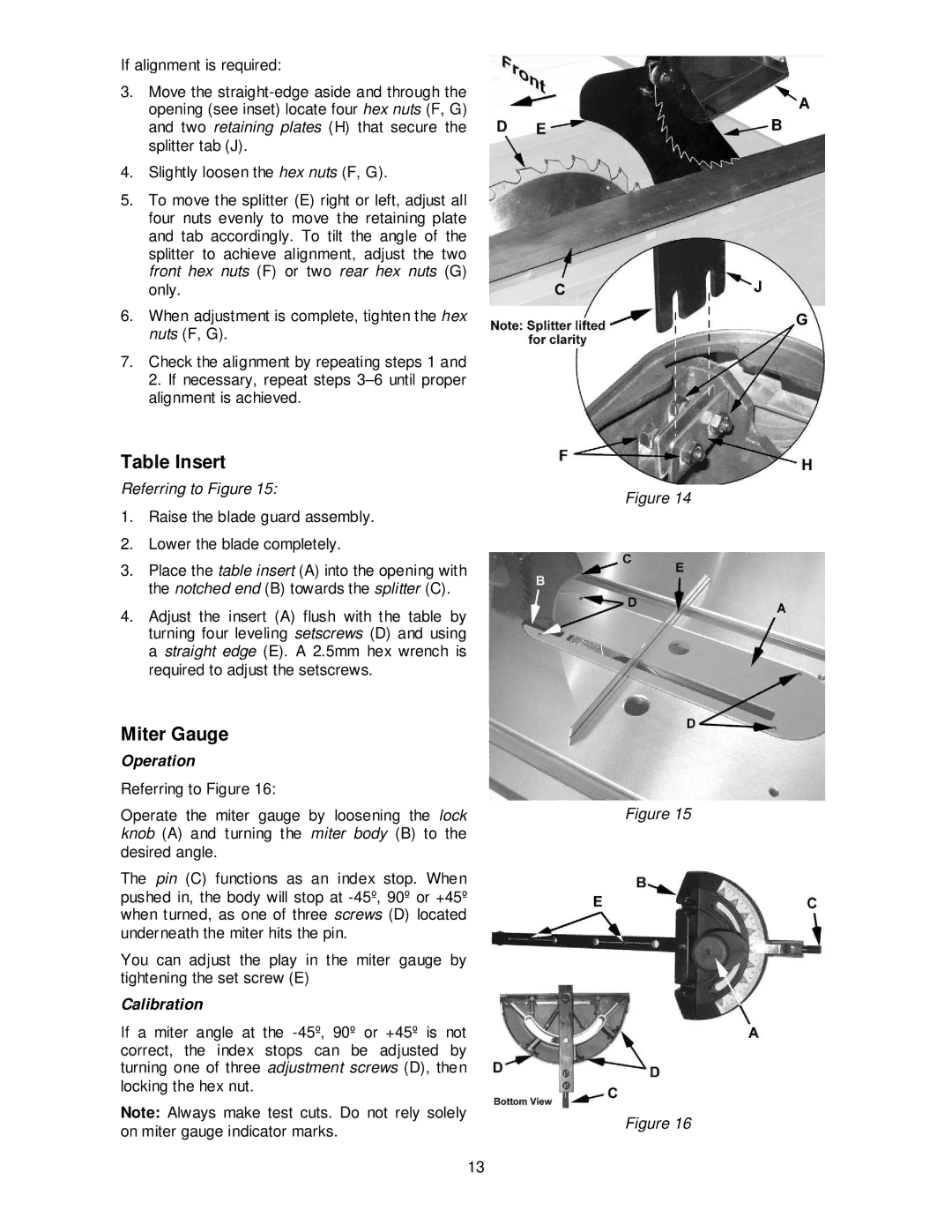
Table Insert
Referring to Figure 15:
1.Raise the blade guard assembly.
2.Lower the blade completely.
3.Place the table insert (A) into the opening with the notched end (B) towards the splitter (C).
4.Adjust the insert (A) flush with the table by turning four leveling setscrews (D) and using a straight edge (E). A 2.5mm hex wrench is required to adjust the setscrews.
Miter Gauge
Operation
Referring to Figure 16:
Operate the miter gauge by loosening the lock knob (A) and turning the miter body (B) to the desired angle.
The pin (C) functions as an index stop. When pushed in, the body will stop at
You can adjust the play in the miter gauge by tightening the set screw (E)
Calibration
If a miter angle at the
Note: Always make test cuts. Do not rely solely on miter gauge indicator marks.
Figure 14
Figure 15
Figure 16
13