If adjustment is required:
10.Back out the 45º adjust setscrew (turn counterclockwise) one or two turns with a 4mm hex wrench (F, Fig. 20).
11.Turn the blade tilting handwheel until the blade is exactly 45º.
12.Tighten the 45º adjust setscrew until it stops, but do not force.
Check to make sure that the blade tilt pointer on the front of the saw properly indicates 45º or 0º (90º). If not, loosen screw and adjust until the pointer indicates properly.
Table to Blade Alignment
The table has been set square with the blade at the factory and no adjustment is necessary now. As the saw receives extensive use, however, table/blade squareness should be checked occasionally and corrected if necessary. Use the miter slot to do this:
1.Raise the blade to maximum height.
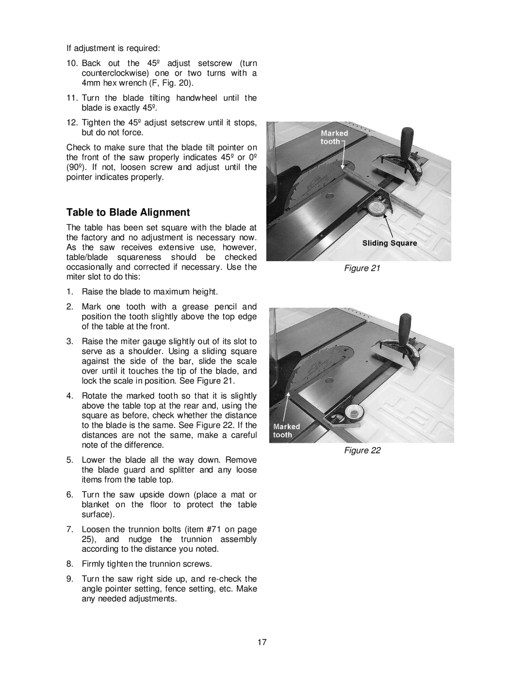
2.Mark one tooth with a grease pencil and position the tooth slightly above the top edge of the table at the front.
3.Raise the miter gauge slightly out of its slot to serve as a shoulder. Using a sliding square against the side of the bar, slide the scale over until it touches the tip of the blade, and lock the scale in position. See Figure 21.
4.Rotate the marked tooth so that it is slightly above the table top at the rear and, using the square as before, check whether the distance to the blade is the same. See Figure 22. If the distances are not the same, make a careful note of the difference.
5.Lower the blade all the way down. Remove the blade guard and splitter and any loose items from the table top.
6.Turn the saw upside down (place a mat or blanket on the floor to protect the table surface).
7.Loosen the trunnion bolts (item #71 on page 25), and nudge the trunnion assembly according to the distance you noted.
8.Firmly tighten the trunnion screws.
9.Turn the saw right side up, and
Figure 21
Figure 22
17