Adjustments
 Disconnect saw from power source before making adjustments.
Blade Raising and Tilt Mechanism
![]() Never try to force the tilting mechanism past the 45º or 90º stops. This may cause the blade to go out of alignment.
Never try to force the tilting mechanism past the 45º or 90º stops. This may cause the blade to go out of alignment.
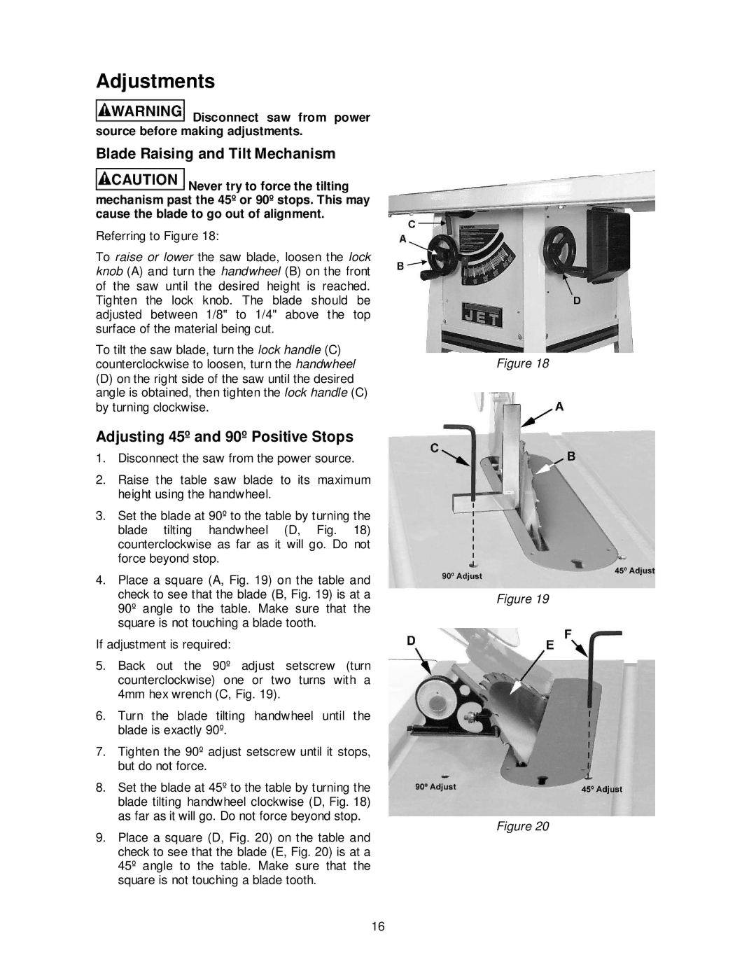
Referring to Figure 18:
To raise or lower the saw blade, loosen the lock knob (A) and turn the handwheel (B) on the front of the saw until the desired height is reached. Tighten the lock knob. The blade should be adjusted between 1/8" to 1/4" above the top surface of the material being cut.
To tilt the saw blade, turn the lock handle (C) counterclockwise to loosen, turn the handwheel
(D)on the right side of the saw until the desired angle is obtained, then tighten the lock handle (C) by turning clockwise.
Adjusting 45º and 90º Positive Stops
1.Disconnect the saw from the power source.
2.Raise the table saw blade to its maximum height using the handwheel.
3.Set the blade at 90º to the table by turning the blade tilting handwheel (D, Fig. 18) counterclockwise as far as it will go. Do not force beyond stop.
4.Place a square (A, Fig. 19) on the table and check to see that the blade (B, Fig. 19) is at a 90º angle to the table. Make sure that the square is not touching a blade tooth.
If adjustment is required:
5.Back out the 90º adjust setscrew (turn counterclockwise) one or two turns with a 4mm hex wrench (C, Fig. 19).
6.Turn the blade tilting handwheel until the blade is exactly 90º.
7.Tighten the 90º adjust setscrew until it stops, but do not force.
8.Set the blade at 45º to the table by turning the blade tilting handwheel clockwise (D, Fig. 18) as far as it will go. Do not force beyond stop.
9.Place a square (D, Fig. 20) on the table and check to see that the blade (E, Fig. 20) is at a 45º angle to the table. Make sure that the square is not touching a blade tooth.
16
Figure 18
Figure 19
Figure 20