Chapter 2 Installing the Device
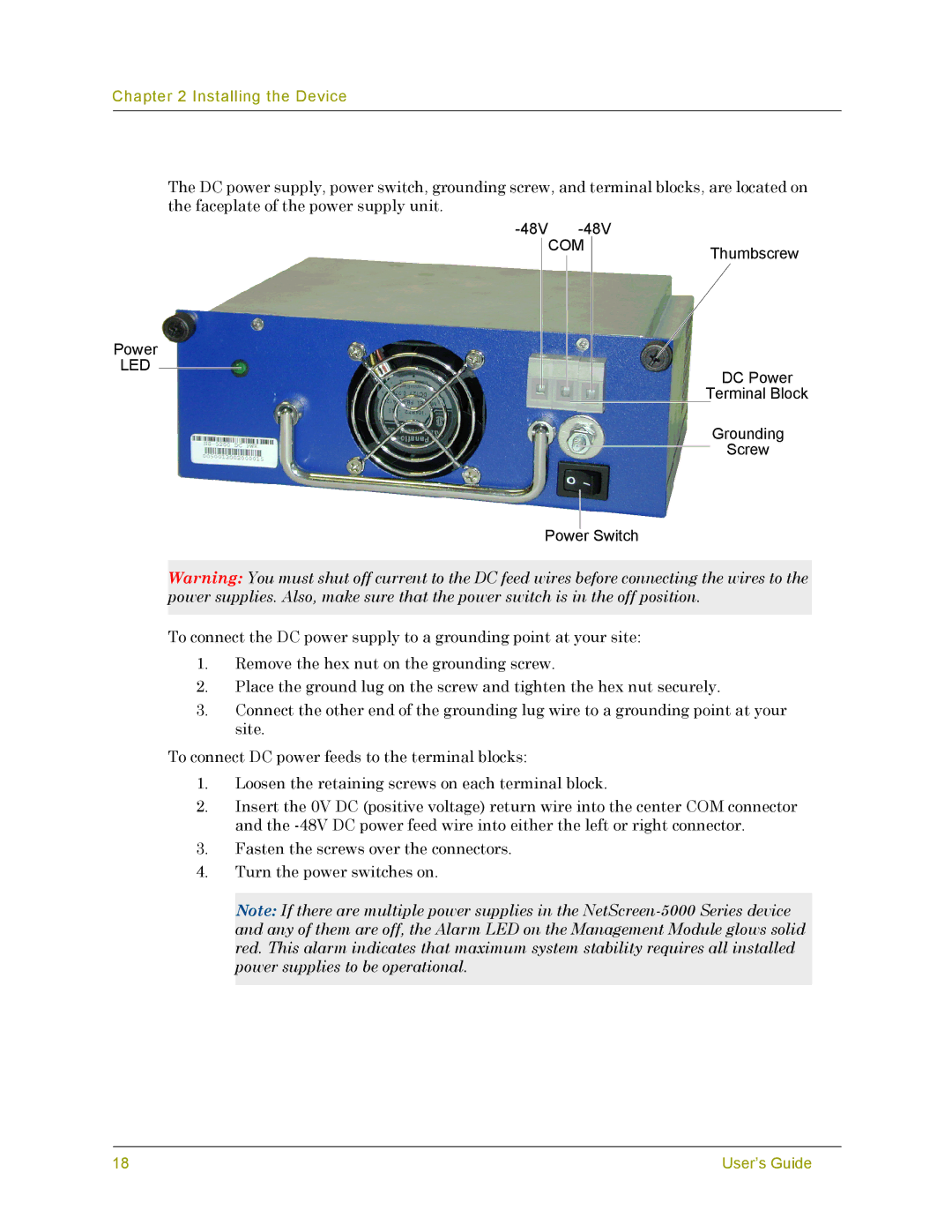
The DC power supply, power switch, grounding screw, and terminal blocks, are located on the faceplate of the power supply unit.
-48V -48V
COMThumbscrew
Power
LED
DC Power
Terminal Block
Grounding
Screw
Power Switch
Warning: You must shut off current to the DC feed wires before connecting the wires to the power supplies. Also, make sure that the power switch is in the off position.
To connect the DC power supply to a grounding point at your site:
1.Remove the hex nut on the grounding screw.
2.Place the ground lug on the screw and tighten the hex nut securely.
3.Connect the other end of the grounding lug wire to a grounding point at your site.
To connect DC power feeds to the terminal blocks:
1.Loosen the retaining screws on each terminal block.
2.Insert the 0V DC (positive voltage) return wire into the center COM connector and the
3.Fasten the screws over the connectors.
4.Turn the power switches on.
Note: If there are multiple power supplies in the
18 | User’s Guide |