Menu Configuration—SET-UP MENU
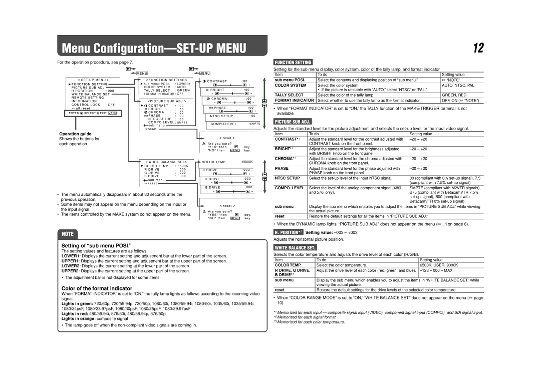
For the operation procedure, see page 7.
Operation guide Shows the buttons for each operation.
•The menu automatically disappears in about 30 seconds after the previous operation.
•Some items may not appear on the menu depending on the input or the input signal.
• The items controlled by the MAKE system do not appear on the menu.
NOTE
Setting of “sub menu POSI.”
The setting values and features are as follows.
LOWER1: Displays the current setting and adjustment bar at the lower part of the screen.
UPPER1: Displays the current setting and adjustment bar at the upper part of the screen.
LOWER2: Displays the current setting at the lower part of the screen.
UPPER2: Displays the current setting at the upper part of the screen.
• The adjustment bar is not displayed for some items.
Color of the format indicator
When “FORMAT INDICATOR” is set to “ON,” the tally lamp lights as follows according to the incoming video signal.
Lights in green: 720/60p, 720/59.94p, 720/50p, 1080/60i, 1080/59.94i, 1080/50i, 1035/60i, 1035/59.94i, 1080/24psF, 1080/23.97psF, 1080/30psF, 1080/25psF, 1080/29.97psF
Lights in red: 480/59.94i, 576/50i, 480/59.94p, 576/50p
Lights in orange: composite signal
|
|
| 12 |
FUNCTION SETTING |
|
|
|
Setting for the sub menu display, color system, color of the tally lamp, and format indicator |
| ||
Item | To do | Setting value | |
sub menu POSI. | Select the contents and displaying position of “sub menu.” | ☞ “NOTE” | |
COLOR SYSTEM | Select the color system. | AUTO, NTSC, PAL | |
|
| • If the picture is unstable with “AUTO,” select “NTSC” or “PAL.” |
|
TALLY SELECT | Select the color of the tally lamp. | GREEN, RED | |
FORMAT INDICATOR | Select whether to use the tally lamp as the format indicator. | OFF, ON (☞ “NOTE”) | |
•When “FORMAT INDICATOR” is set to “ON,” the TALLY function of the MAKE/TRIGGER terminal is not available.
PICTURE SUB ADJ.
Adjusts the standard level for the picture adjustment and selects the
Item | To do | Setting value |
CONTRAST*1 | Adjust the standard level for the contrast adjusted with | |
| CONTRAST knob on the front panel. |
|
BRIGHT*1 | Adjust the standard level for the brightness adjusted | |
| with BRIGHT knob on the front panel. |
|
CHROMA*1 | Adjust the standard level for the chroma adjusted with | |
| CHROMA knob on the front panel. |
|
PHASE | Adjust the standard level for the phase adjusted with | |
| PHASE knob on the front panel. |
|
NTSC SETUP | Select the | 00 (compliant with 0% |
|
| (compliant with 7.5% |
COMPO. LEVEL | Select the level of the analog component signal (480i | SMPTE (compliant with M2VTR signals), |
| and 576i only). | B75 (compliant with BetacamVTR 7.5% |
|
| |
|
| BetacamVTR 0% |
sub menu | Display the sub menu which enables you to adjust the items in “PICTURE SUB ADJ.” while viewing | |
| the actual picture. |
|
reset | Restore the default settings for all the items in “PICTURE SUB ADJ.” | |
• When the DYNAMIC lamp lights, “PICTURE SUB ADJ.” does not appear on the menu (☞ t on page 6).
H. POSITION*2 Setting value:
Adjusts the horizontal picture position.
WHITE BALANCE SET.
Selects the color temperature and adjusts the drive level of each color (R/G/B).
Item | To do | Setting value |
COLOR TEMP. | Select the color temperature. | 6500K, USER, 9300K |
R DRIVE, G DRIVE, | Adjust the drive level of each color (red, green, and blue). | |
B DRIVE*3 |
|
|
sub menu | Display the sub menu which enables you to adjust the items in “WHITE BALANCE SET.” while | |
| viewing the actual picture. |
|
reset | Restore the default settings for the drive levels of the selected color temperature. | |
•When “COLOR RANGE MODE” is set to “ON,” “WHITE BALANCE SET.” does not appear on the menu (☞ page 10).
*1 Memorized for each input — composite signal input (VIDEO), component signal input (COMPO.), and SDI signal input. *2 Memorized for each signal format.
*3 Memorized for each color temperature.
• The lamp goes off when the