ENGLISH


￿￿


Typical Connections /


/ °“√‡™◊ËÕ¡µËÕ·∫∫ª°µ‘/ WOł–uLM


A


‰∑¬

wÐdŽ

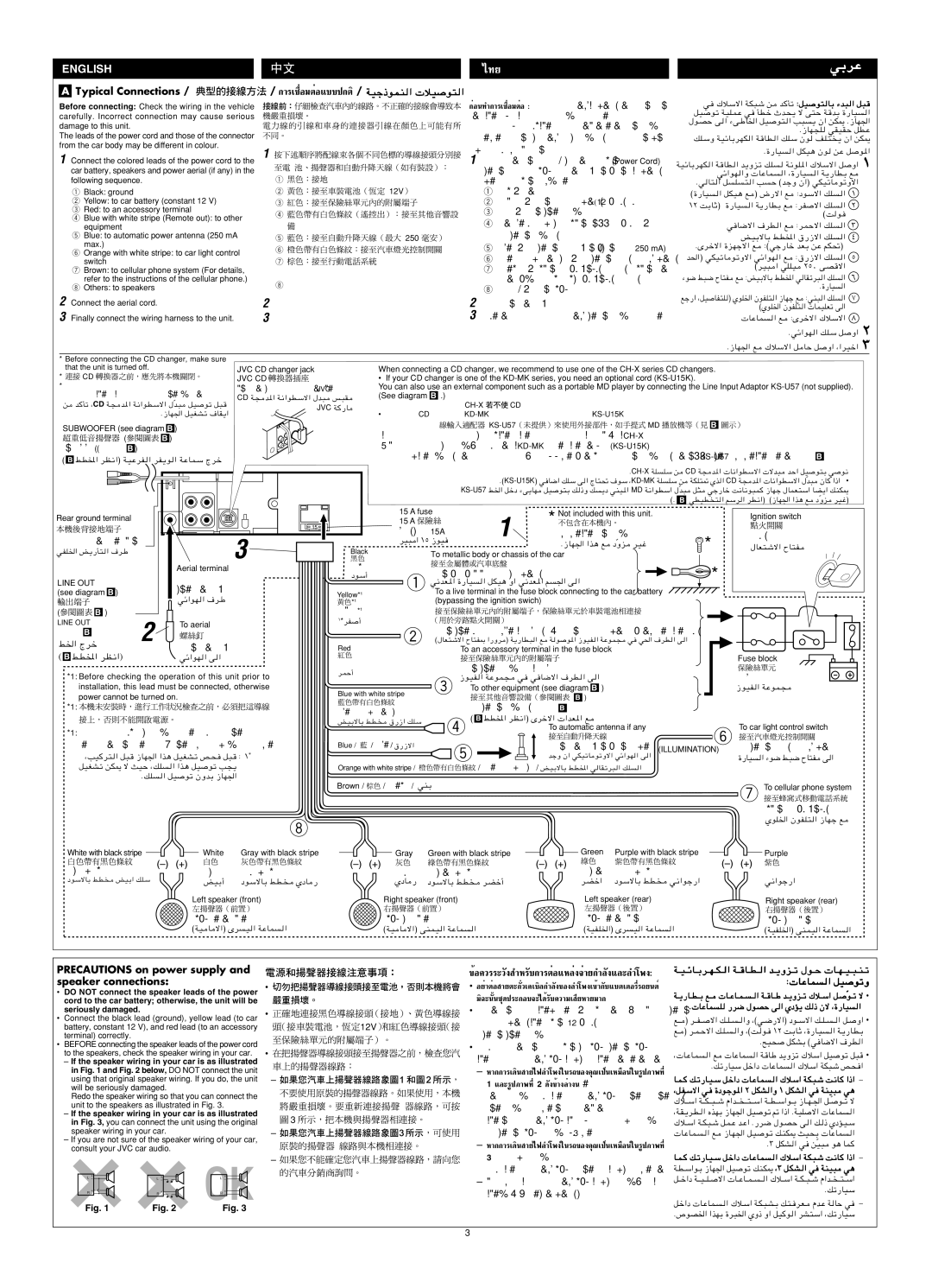
Before connecting: Check the wiring in the vehicle


°ËÕπ∑”°“√‡™◊ËÕ¡µËÕµ√«®: Õ∫°“√‡¥‘𠓬‰ø„π√∂¬πµÏլ˓ß√–¡—¥√–«—ß

w

∫qO


carefully. Incorrect connection may cause serious


լ˓„ÀȺ‘¥æ≈“¥„π°“√‡™◊ËÕ¡µËÕ™ÿ¥ª√–°Õ∫™ÿ¥π’È


qO


damage to this unit.


°“√‡™◊ËÕ¡µËÕº‘¥æ≈“¥Õ“®∑”„Àȇ°‘¥§«“¡‡

’¬À“¬√È“¬·√ß°—∫™ÿ¥ª√–

‰uBŠ v

Æ“UN−K


The leads of the power cord and those of the connector


°Õ∫π’ȉ¥È “√µ–°—Ë«¢Õß “¬‰ø ·≈–¢ÕßÕÿª°√≥ϵËÕ‡™◊ËÕ¡®“°µ—«∂— pKÝË WOzUÐdNJ


from the car body may be different in colour.


1


ß√∂Õ“®¡’ ’∑’ˉ¡Ë‡À¡◊Õπ°—π


Æ…—UO


1 Connect the colored leads of the power cord to the


(Power Cord)

WOzUÐdNJ

±


car battery, speakers and power aerial (if any) in the

￿￿=


1 ‡™◊ËÕ¡µËÕ “¬µ–°—Ë« ’µË“ß Ê ¢Õß “¬‡§‡∫‘≈°”≈—ß


‡¢È“°—∫·∫µ‡µÕ√’Ë ≈”‚æß ·≈– “¬Õ“°“» Õ—µ‚π¡—µ‘„π√∂¬πµÏ


wz«uN


following sequence.


1


(∂È“¡’) µ“¡≈”¥—∫µËÕ‰ªπ’È


Æw


1 Black: ground


2

=12V￿

1

’¥” : “¬¥‘π


©…—UO


±


2 Yellow: to car battery (constant 12 V)


3


2

’‡À≈◊Õß : µËÕ°—∫·∫µ‡µÕ√’Ë√∂¬πµÏ(12‚«≈∑ϧß∑’Ë)


±≤ XÐUŁ® …—UO


3 Red: to an accessory terminal


4


3

’·¥ß : µËÕ°—∫¢—È« Ë«πª√–°Õ∫


©X


4 Blue with white stripe (Remote out): to other


w


equipment


￿


4

“¬ ’øÈ“∑’Ë¡’·∂∫¢“« ( ”À√—∫ —≠≠“≥√’‚¡∑ÕÕ°):


5 Blue: to automatic power antenna (250 mA

5

=250


µËÕ‡¢È“°—∫Õÿª°√≥ÏÕ◊Ëπ


iOÐôUÐ jD<« ‚—“ô« pK

¥


max.)


6


5

’øÈ“ : µËÕ‡¢È“°—∫‡ “Õ“°“»Õ—(µ‚¢π“¡—¥ µŸß ÿ250¥

mA)


ÆÈdšô« …eNłô« l


6 Orange with white stripe: to car light control


µ


7


6


b(«® wJOðU


switch


È¡·≈–¡’·∂∫≈“¬ ’¢“« : µËÕ‡¢È“°—∫ «‘µ™Ï§«∫§ÿ¡‰ø√∂¬πµÏ

©dO³


7 Brown: to cellular phone system (For details,


7

’πÈ”µ“≈ : ”À√—∫√–∫∫‚∑√»—æ∑χ´≈≈Ÿ≈“√Ï (

”À√—∫√“¬≈–


refer to the instructions of the cellular phone.)

8


‡Õ’¬¥ ‚ª√¥ÕË“π§”·π–π”¢Õß‚∑√»—æ∑χ´≈≈Ÿ≈“√Ï)


¡u{ j³{ ÕU²H


Æ…—UO


8 Others: to speakers


8

’Õ◊Ëπ Ê : µËÕ°—∫≈”‚æß


lł—« ¨qO


2 Connect the aerial cord.


2


2 ‡™◊ËÕ¡µËÕ°—∫ “¬Õ“°“»


©ÍuK)« ÊuHK²


3 Finally connect the wiring harness to the unit.


3


3 ÿ¥∑È“¬ µËÕ Ë«π§«∫§ÿ¡°“√‡¥‘𠓬‰ø‡¢È“°—∫™ÿ¥ª√–°Õ∫™ÿ¥π’È


Æwz«uN


Æ“UN'« l

* Before connecting the CD changer, make sure


that the unit is turned off.


JVC CD changer jack

When connecting a CD changer, we recommend to use one of the CH-X series CD changers.


* ￿￿ CD


JVC CD

• If your CD changer is one of the KD-MK series, you need an optional cord (KS-U15K).


* °ËÕπ®–‡™◊ËÕ¡µËÕ‡§√◊ËÕ߇≈Ëπ´’¥’


À—«‡ ’¬∫¢Õ߇§√◊ËÕ߇≈Ëπ´’JVC¥’ ¬’ËÀÈÕ

You can also use an external component such as a portable MD player by connecting the Line Input Adaptor KS-U57 (not supplied).

°√ÿ≥“µ√«® Õ∫„ÀÈ·πË„®«Ë“‡§√◊ËÕ߇≈Ëπ´’¥’π—Èπª‘¥Õ¬

CD W−


(See diagram

B

.)


s


CD W−


b³Ò


JVC W


CH-X

CD


Æ“UN'« qOGAð ·UI¹«


CD

KD-MK

KS-U15K ￿


￿￿

=KS-U57

MD


B


SUBWOOFER (see diagram

B

)


„π°“√‡™◊ËÕ¡µËÕ‡§√◊ËÕ߇≈Ëπ´’¥’ ‡√“¢Õ·π–π”„Àȧÿ≥„™È‡§√◊ËÕ߇≈Ëπ´’¥’√ÿËπ„CH-X¥√ÿËπÀπ÷Ëß„πµ√–°Ÿ≈


=(


)


B


´—∫«Ÿø‡øÕ√Ï(¥Ÿ·ºπ¿Ÿ¡


)


ë À“°‡§√◊ËÕ߇≈Ëπ´’¥’¢Õߧÿ≥‡ªÁπ√ÿËπ∑’ËÕ¬ŸË„πµ√KD-MK§ÿ≥µÈÕß„™È–°Ÿ≈ “¬‡æ‘Ë¡‡µ‘¡(KS-U15K)


B


©


jD<« dE½«® WOŽdH « dH¹u « WŽULÝ Ãdš


§ÿ≥

“¡“√∂„™ÈÕÿª°√≥Ï¿“¬πÕ°‡™Ëπ‡§√◊ËÕ߇≈Ëπ‡ÕÁ¡¥’·∫∫æ°æ“‰¥È ‚¥¬π”¡“‡™◊ËÕ¡µËÕ°—∫Õ·¥ª‡µÕ√ÏKS-U57“¬ —(‰¡Ë‰≠≠“≥‡¥È„ÀÈ¡“¢È“ ¥È«¬) (¥Ÿ·

ºπB

¿Ÿ¡)


B


ÆCH-X WK


CD W−


Æ©KS-U15K® w U{« pKÝ v « ÃU²% ·uÝ ¨KD-MKWK

KÝ s

WJK²9 Íc « CD W− b*« U½«uDÝô« ‰bÒ³ ÊU «–«


KS-U57j)« qšœ ¡v¹UN

MD W½«uDÝ« ‰Òb³


©Æ

B

wDOD


ËeÒ


Rear ground terminal


15 A fuse

1

*

Not included with this unit.


Ignition switch


15 A


15


ø‘« Ï¢π“15A¥


‰¡Ë‰¥È„ÀÈ¡“°—∫™ÿ¥ª√–°Õ∫π


«‘∑™Ï®ÿ¥√–‡∫‘¥

®ÿ¥‡™◊ËÕ¡µËÕ “¬¥‘π¥È“πÀ≈—ß

3


*

￿￿

dO³ « ±µ “uO


Æ“UN'« «c¼ l

ÒËe

‰UF²ýô« ÕU²H


wHK)« i¹—Q²


Black

To metallic body or chassis of the car


Aerial terminal


’¥”


µËÕ°—∫‚§√ß‚≈À–À√◊Õ‡™ ´‘ ¢Õß√∂¬πµÏ


*


LINE OUT


œuÝ√

1


¢—È« “¬Õ“°“»


w½bF*« …—UO


(see diagram B )


1

To a live terminal in the fuse block connecting to the car battery


wz«uN


Yellow*


(bypassing the ignition swich)


￿￿*1


(

B )


1


2


’‡À≈◊Õß*


LINE OUT

To aerial


±*dH


µËÕ°—∫¢—È«∑’Ë¡’°√–· ‰øøÈ“„π·ºßø‘« Ï ´÷ËßµËÕ°—∫·∫µ‡µÕ√’Ë√∂¬πµ (‚¥¬‰¡ËµÈÕß„™È «‘∑™Ï®ÿ¥√–‡∫‘¥)

(¥Ÿ·ºπ¿¡‘B )


2

j)« Ãdš

µËÕ°—∫ “¬Õ“°“»


Red

©‰UF²ýô« ÕU²H0 «—Ëd ® W¹—UD³ « l

W u

u*« “uOH « WŽuL− w w(« ·dD « v «


To an accessory terminal in the fuse block


( B jD<« dE½«)


wz«uN


￿￿


Fuse block


’·¥ß


µËÕ°—∫¢—È« Ë«πª√–°Õ∫„π·ºßø‘«


*1: Before checking the operation of this unit prior to

dLŠ√


·ºßø‘«


3

“uOH


installation, this lead must be connected, otherwise

Blue with white stripe


To other equipment (see diagram B )


“uOH


power cannot be turned on.


= B )


*1:


’øÈ“·≈–¡’·∂∫≈“¬ ’¢“«


µËÕ‡¢È“°—∫Õÿª°√≥ÏÕ◊Ëπ(¥BŸ·ºπ¿Ÿ¡)


© B jD<« dE½«® Èdšô«


iOÐôUÐ jD


4


To car light control switch


*1: °ËÕπ°“√µ√«® Õ∫°“√∑”ß“π¢Õß™ÿ¥ª√–°Õ∫π’È°ËÕπ∑’Ë®–µ‘¥µ—Èß


To automatic antenna if any

6


µËÕ‡¢È“°—∫ «‘µ™Ï§«∫§ÿ¡‰ø√∂¬πµ


µÈÕßµËÕ “¬µ–°—Ë«π’È°ËÕπ ¡‘©–π—Èπ®–‰¡Ë “¡“√∂‡ª‘¥‡§√◊ËÕ߉¥È

Blue / ￿=L=

’øÈ“L ‚—“ô«


5

µËÕ°—∫ “¬Õ“°“»Õ—µ‚π¡—µ‘ (∂È“¡’)(ILLUMINATION)


¨VO


¿


błË Ê« wJOðU


…—UO « ¡u{ j³{ ÕU²H v «


∫ ±


qOGAð sJ1 ô YOŠ ¨pK


Orange with white stripe /=


/ È¡·≈–¡’·∂∫/¢iOÐôUГ«

jD<« w


ÆpK


Brown / ￿￿ / ’πÈ”µ“≈/ wMÐ


7 To cellular phone system


”À√—∫√–∫∫‚∑√»—æ∑χ´≈≈Ÿ≈“√


8


ÍuK)« ÊuHK²


White with black stripe

White

Gray with black stripe


Gray

Green with black stripe


Green

Purple with black stripe


Purple


’¢“«·∂∫¥”


￿￿

’‡∑“·∂∫¥”


￿￿

’‡¢’¬«·∂∫¥”


￿￿


￿￿


’¢“«


’‡∑“


’‡¢’¬« ’¡Ë«ß·∂∫¥”


’¡Ë«ß


œuÝôUÐ jD


iOÐ√

œuÝôUÐ jD


ÍœU

œuÝôUÐ jD


dCš«

œuÝôUÐ jD


w½«uł—«


Left speaker (front)


Right speaker (front)


Left speaker (rear)


Right speaker (rear)


≈”‚æß´È“¬ (ÀπÈ“)


≈”‚æߢ«“ (ÀπÈ“)


≈”‚æß´È“¬ (À≈—ß)


≈”‚æߢ«“ (À≈—ß)


©WO


©WO


©WOHK)«® Èd


©WOHK)«® vMLO « WŽUL «

PRECAUTIONS on power supply and speaker connections:

DO NOT connect the speaker leads of the power cord to the car battery; otherwise, the unit will be seriously damaged.

Connect the black lead (ground), yellow lead (to car battery, constant 12 V), and red lead (to an accessory terminal) correctly.

BEFORE connecting the speaker leads of the power cord to the speakers, check the speaker wiring in your car.

If the speaker wiring in your car is as illustrated in Fig. 1 and Fig. 2 below, DO NOT connect the unit using that original speaker wiring. If you do, the unit will be seriously damaged.

Redo the speaker wiring so that you can connect the unit to the speakers as illustrated in Fig. 3.

If the speaker wiring in your car is as illustrated in Fig. 3, you can connect the unit using the original speaker wiring in your car.

If you are not sure of the speaker wiring of your car, consult your JVC car audio.

+

+

+

+

+

+


L -

-

L -

-

L -

-

+

+

+

+

+

+


R -

-

R -

-

R -

-

Fig. 1

Fig. 2


Fig. 3


￿

12V￿

￿￿


￿


N ￿￿O ￿￿￿


=

￿3

P￿￿

=

W???O???zU???Ðd???N???J???W???b???¹Ëe???ð ‰u???Š

¢ÈÕ§«√√–«—ß ”À√—∫°“√µËÕ·À≈Ë߮˓¬°”≈—ß·≈–≈”‚æß:

լ˓µËÕ “¬µ–°—Ë«‡§‡∫‘≈°”≈—ߢÕß≈”‚æ߇¢È“°—∫·∫µ‡µÕ√’Ë√∂¬πµÏ

¡‘©–π—Èπ™ÿ¥ª√–°Õ∫®–‰¥È√—∫§«“¡‡ ’¬À“¬¡“°

W???¹—U???D???Ð l???W???b???¹Ëe???ð „ö???Ý« q??

u???ðÒÒ ô

µËÕ “¬µ–°—Ë«·µË≈– ’„ÀÈ∂Ÿ°µÈÕß : ’¥” ( “¬¥‘π), ’‡À≈◊Õß (‡Æ¢È“°—

∫·∫µ‡µÕ√’Ë√∂¬πµÏ„ÀÈ¡’°”≈12—ߧß∑’Ë‚«≈∑Ï) ·≈– ’·¥ß

l????


(‡¢È“°—∫¢—È« Ë«πª√–°Õ∫)

l??

Æ`O×


°ËÕπ∑’Ë®–µËÕ “¬µ–°—Ë«‡§‡∫‘≈°”≈—ߢÕß≈”‚æ߇¢È“°—∫≈”‚æß


¨


„Àȵ√«® Õ∫°“√‡¥‘𠓬‰ø≈”‚æß„π√∂¢Õߧÿ≥„Àȇ√’¬∫√ÈÕ¬‡ ’¬°ËÕπ


Æpð—UOÝ qš«œ


À“°°“√‡¥‘𠓬‰ø≈”‚æß„π√∂¢Õߧÿ≥‡ªÁπ‡À¡◊Õπ„π√Ÿª¿“æ∑’Ë


1 ·≈–√Ÿª¿“æ∑’Ë2¥—ߢȓß≈Ë“ßπ’È

U??L??


¨q?H?Ýô« w?


լ˓µËÕ™ÿ¥ª√–°Õ∫∑’Ë„™È°“√‡¥‘𠓬‰ø≈”‚æß·∫∫¥—È߇¥‘¡π—Èπ ¡‘©–


Ò

π—Èπ™ÿ¥ª√–°Õ∫®–‰¥È√—∫§«“¡‡ ’¬À“¬¡“°

„ö????Ý« W????J????³????ý «b????


¨W?I?¹d?D?


„ÀÈ®—¥°“√‡¥‘𠓬‰ø≈”‚æß„À¡Ë ‡æ◊ËÕ§ÿ≥®– “¡“√∂µËÕ™ÿ¥ª√–


°Õ∫‡¢È“°—∫≈”‚æßµ“¡√Ÿª¿“æ∑’Ë3‰¥È

„ö??Ý« W??J?³?ý q?L?Ž b?Ž« Æ—d?{ ‰u?B?Š v?


Æ≥ qJA

ÒO³

À“°°“√‡¥‘𠓬‰ø≈”‚æß„π√∂¢Õߧÿ≥‡ªÁπ‡À¡◊Õπ„π√Ÿª¿“æ∑’Ë

3 §ÿ≥ “¡“√∂µËÕ™ÿ¥ª√–

U??L??

¨≥ q?J?A?


W?D?Ý«u?Ð “UN'« qO


°Õ∫∑’Ë„™È°“√‡¥‘𠓬‰ø≈”‚æß·∫∫¥—È߇¥‘¡„π√∂¢Õߧÿ≥‰¥È‡≈¬


q????š«œ W????O????K???


À“°§ÿ≥‰¡Ë·πË„®«Ë“°“√‡¥‘𠓬‰ø≈”‚æß„π√∂¢Õߧÿ≥‡ªÁπ·∫∫„¥


Æpð—UOÝ

„ÀȪ√÷°…“ºŸÈ¢“¬√∂¬πµÏ¢Õߧÿ≥


q?š«œ


Æ’uB)« «cNÐ …d³)« ÍË– Ë« qO


3

Page 51
Image 51
JVC IKD-LH2000 Before connecting Check the wiring in the vehicle, Carefully. Incorrect connection may cause serious, Max

IKD-LH2000 specifications

The JVC IKD-LH2000 is a versatile and feature-rich high-definition camera designed specifically for broadcast and professional applications. With its advanced imaging capabilities and robust build quality, it is an ideal choice for users looking for reliability and exceptional video performance.

One of the standout features of the IKD-LH2000 is its high-resolution imaging sensor, which delivers stunning image quality with remarkable clarity and color accuracy. This camera supports full HD video capture at 1080p, ensuring that every detail is captured crisply, making it perfect for a range of applications from live broadcasts to corporate events.

The camera is equipped with an advanced image processing engine that enhances video quality in various lighting conditions, delivering excellent performance even in low-light situations. This technology allows for smooth and clear footage, minimizing noise and maximizing detail, making it a great choice for both indoor and outdoor environments.

Another notable characteristic of the JVC IKD-LH2000 is its extensive connectivity options. The camera features multiple output interfaces, including HDMI, SDI, and USB, allowing seamless integration with various video equipment, such as live switchers and recording devices. This versatility ensures that the camera can be easily incorporated into any production workflow, whether it’s for live streaming or post-production.

Moreover, the IKD-LH2000 is designed with user-friendliness in mind. It includes an intuitive control panel that allows operators to make adjustments quickly and efficiently. Additionally, the camera supports remote operation, enabling users to control camera settings from a distance, which is particularly useful in multi-camera setups.

Durability is another significant factor in the design of the JVC IKD-LH2000. Constructed with a rugged chassis, the camera is built to withstand the challenges of various production environments, including heavy usage and transport. This robust design ensures that the camera can keep up with the demands of professional settings.

In summary, the JVC IKD-LH2000 combines high-definition video quality, advanced imaging technologies, versatile connectivity options, user-friendly controls, and durable construction. It is an exceptional choice for professionals seeking a reliable and powerful camera to enhance their broadcasting and production capabilities.