2. CONTROLS, INDICATIONS AND CONNECTORS
Camera Control [Panel side]
|
|
| 6 | 8 | 9 |
|
|
|
|
|
| LOCK | MENU | ITEM+ | DATA+ |
|
|
|
|
|
| ON |
|
|
|
|
|
|
|
|
|
|
| BARS |
|
|
|
| |
1 2 3 4 | RESET |
| SET | ITEM- | DATA- |
|
|
|
|
ON |
| OFF |
|
|
|
|
|
|
|
12 | 11 | 10 | 7 |
| 5 |
| 4 | 3 | 2 |
|
|
|
|
|
| ||||
|
|
|
|
|
| CAMERA CONTROL UNIT | |||
| PULL OPEN |
| MENU |
| FILES |
| FREEZE | ||
|
| 1 | 2 | 3 | 4 |
| |||
|
|
|
|
|
| ||||
13 |
|
|
|
| SELECT |
|
| MEMORY |
|
|
|
|
|
|
|
|
|
| POWER |
TO CAMERA | WHITE PAINT | VIDEO LEVEL |
SET | FULL AUTO | LEVEL |
ON
RB
14 | OFF |
|
1
PAINT
15 | 16 | 17 | 18 | 19 |
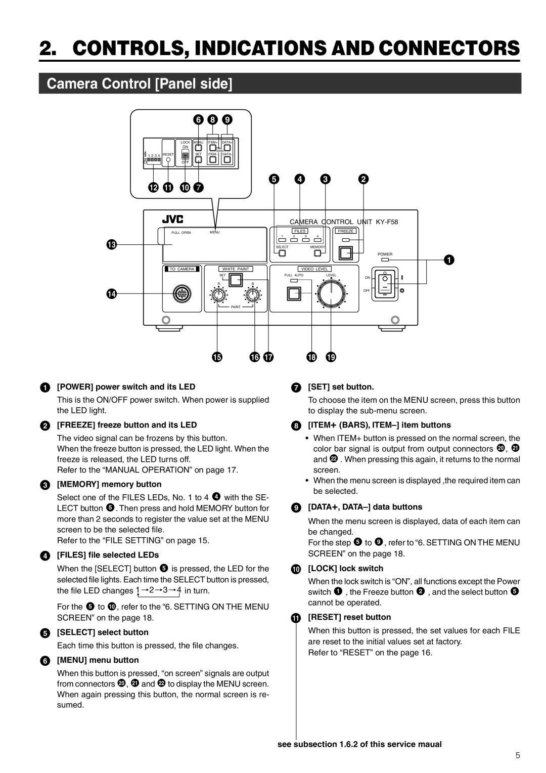
1 [POWER] power switch and its LED |
|
| 7 [SET] set button. | |
This is the ON/OFF power switch. When power is supplied the LED light.
2[FREEZE] freeze button and its LED
The video signal can be frozens by this button.
When the freeze button is pressed, the LED light. When the freeze is released, the LED turns off.
Refer to the “MANUAL OPERATION” on page 17.
3[MEMORY] memory button
Select one of the FILES LEDs, No. 1 to 4 4 with the SE- LECT button 5 . Then press and hold MEMORY button for more than 2 seconds to register the value set at the MENU screen to be the selected file.
Refer to the “FILE SETTING” on page 15.
4[FILES] file selected LEDs
When the [SELECT] button 5 is pressed, the LED for the selected file lights. Each time the SELECT button is pressed, the file LED changes 1 ![]() 2
2 ![]() 3
3 ![]() 4 in turn.
4 in turn.
For the 5 to 10 , refer to the “6. SETTING ON THE MENU SCREEN” on the page 18.
5[SELECT] select button
Each time this button is pressed, the file changes.
6[MENU] menu button
When this button is pressed, “on screen” signals are output from connectors 20 , 21 and 22 to display the MENU screen. When again pressing this button, the normal screen is re- sumed.
To choose the item on the MENU screen, press this button to display the
8[ITEM+ (BARS), ITEM–] item buttons
•When ITEM+ button is pressed on the normal screen, the color bar signal is output from output connectors 20 , 21 and 22 . When pressing this again, it returns to the normal screen.
•When the menu screen is displayed ,the required item can be selected.
9[DATA+, DATA–] data buttons
When the menu screen is displayed, data of each item can be changed.
For the step 5 to 9 , refer to “6. SETTING ON THE MENU SCREEN” on the page 18.
10[LOCK] lock switch
When the lock switch is “ON”, all functions except the Power switch 1 , the Freeze button 2 , and the select button 5 cannot be operated.
11[RESET] reset button
When this button is pressed, the set values for each FILE are reset to the initial values set at factory.
Refer to “RESET” on the page 16.
see subsection 1.6.2 of this service maual
5