Introduction
Name of Parts
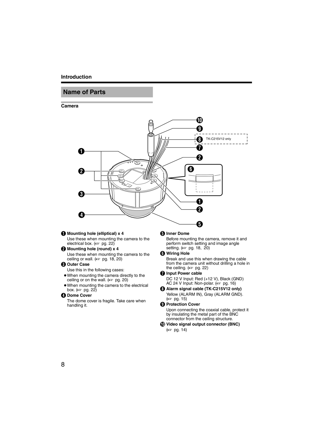
Camera
A
B
C
D
A Mounting hole (elliptical) x 4
Use these when mounting the camera to the electrical box. (A pg. 22)
B Mounting hole (round) x 4
Use these when mounting the camera to the ceiling or wall. (A pg. 18, 20)
C Outer Case
Use this in the following cases:
●When mounting the camera directly to the ceiling or on the wall. (A pg. 20)
●When mounting the camera to the electrical box. (A pg. 22)
D Dome Cover
The dome cover is fragile. Take care when handling it.
J
I
H
G
B
F
A
B
E
E Inner Dome
Before mounting the camera, remove it and perform switch setting and image angle setting. (A pg. 18, 20)
F Wiring Hole
Break and use this when drawing the cable from the camera unit without drilling a hole in the ceiling. (A pg. 22)
G Input Power cable
DC 12 V Input: Red (+12 V), Black (GND)
AC 24 V Input:
HAlarm signal cable
Yellow (ALARM IN), Gray (ALARM GND). (A pg. 15)
IProtection Cover
Upon connecting the coaxial cable, protect it by insulating the metal part of the BNC connector from the ceiling structure.
JVideo signal output connector (BNC) (A pg. 14)
8