VR-N100U specifications
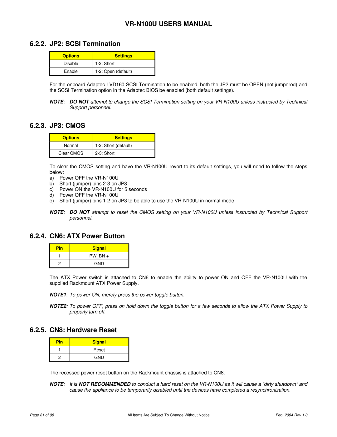
The JVC VR-N100U is a state-of-the-art network video recorder designed to enhance the efficiency and functionality of modern surveillance systems. With its robust architecture and a suite of advanced features, this device meets the demands of both commercial and residential applications.One of the standout features of the VR-N100U is its ability to support high-definition video recording. The device can handle resolutions up to 4K, which ensures that users receive crystal-clear footage. This is particularly beneficial for identifying details in critical incidents, enhancing overall security measures.
The VR-N100U is equipped with an intuitive user interface that makes it easy for operators to navigate through various settings and functionalities. It supports seamless integration with JVC’s line of IP cameras, allowing for a flexible and scalable surveillance solution. The NVR can manage multiple cameras simultaneously, enabling users to monitor several areas in real-time.
A key technological feature of this model is its advanced compression capabilities. The VR-N100U supports H.264 and H.265 compression formats, which optimize storage requirements without compromising video quality. This is especially advantageous in environments with limited storage capacity, as it maximizes the retention period of recorded footage.
Another critical characteristic of the JVC VR-N100U is its built-in redundancy options. It offers RAID configurations that enhance fault tolerance, ensuring that critical data remains secure even in the event of a hardware failure. This level of reliability is essential for security operations, where data integrity and availability are paramount.
Additionally, the NVR provides remote access capabilities, allowing users to view live footage and recorded content from anywhere via the internet. This feature enhances the flexibility of monitoring and allows for timely responses to potential security threats. The JVC VR-N100U is also compatible with mobile applications, offering users the convenience of managing their surveillance systems directly from their smartphones or tablets.
With PoE (Power over Ethernet) support, installation is streamlined, as the device can receive power and data through a single Ethernet cable. This eliminates the need for additional power adapters, simplifying the setup process.
In summary, the JVC VR-N100U is an excellent choice for those looking to implement a reliable and high-performance network video recording solution. Its impressive features, advanced technology, and user-friendly interface make it a valuable asset in any security system. Whether for business or home use, the VR-N100U delivers exceptional performance and peace of mind.

