ASSEMBLING THE STAND
Be sure that all parts are included before starting to assemble your unit.
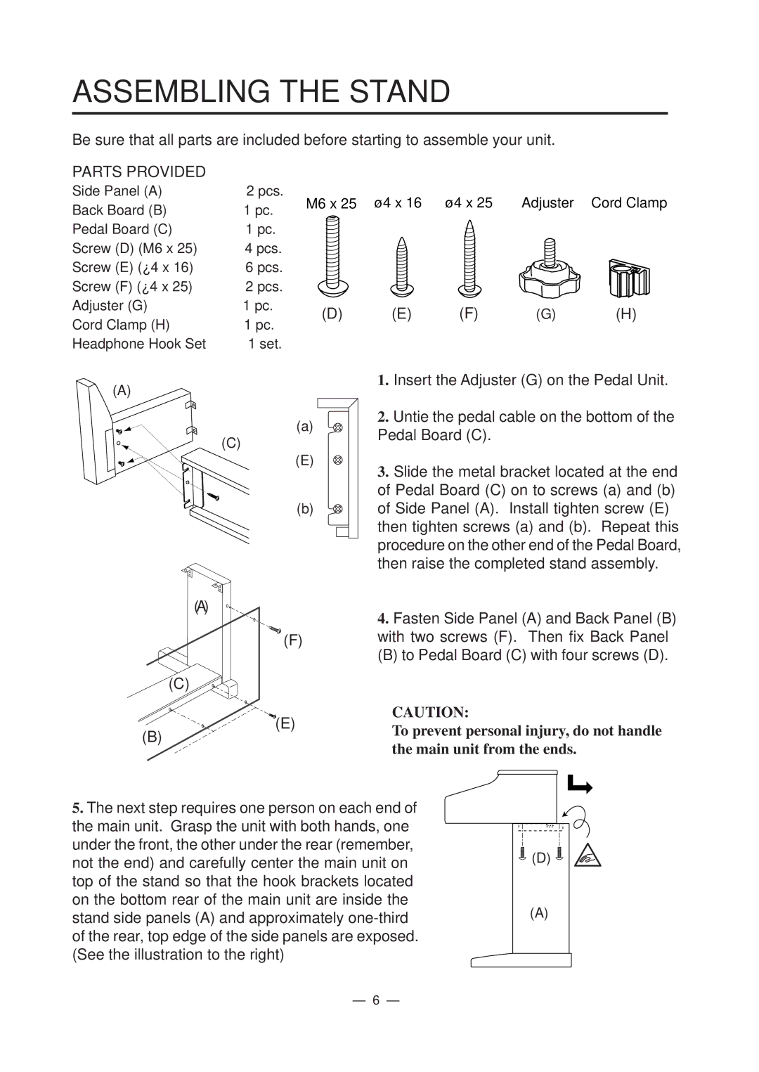
PARTS PROVIDED
Side Panel (A) | 2 pcs. | M6 x 25 | ø4 x 16 | ø4 x 25 | Adjuster | Cord Clamp | |
Back Board (B) | 1 pc. | ||||||
|
|
|
|
| |||
Pedal Board (C) | 1 pc. |
|
|
|
|
| |
Screw (D) (M6 x 25) | 4 pcs. |
|
|
|
|
| |
Screw (E) (ø4 x 16) | 6 pcs. |
|
|
|
|
| |
Screw (F) (ø4 x 25) | 2 pcs. |
|
|
|
|
| |
Adjuster (G) | 1 pc. | (D) | (E) | (F) | (G) | (H) | |
Cord Clamp (H) | 1 pc. | ||||||
|
|
|
|
| |||
Headphone Hook Set | 1 set. |
|
|
|
|
|
(A)
(a)
(C)
(E)
(b)
(A)
(F)
(C)
(E) |
(B)
1.Insert the Adjuster (G) on the Pedal Unit.
2.Untie the pedal cable on the bottom of the Pedal Board (C).
3.Slide the metal bracket located at the end of Pedal Board (C) on to screws (a) and (b) of Side Panel (A). Install tighten screw (E) then tighten screws (a) and (b). Repeat this procedure on the other end of the Pedal Board, then raise the completed stand assembly.
4.Fasten Side Panel (A) and Back Panel (B) with two screws (F). Then fix Back Panel
(B) to Pedal Board (C) with four screws (D).
CAUTION:
To prevent personal injury, do not handle the main unit from the ends.
5.The next step requires one person on each end of the main unit. Grasp the unit with both hands, one under the front, the other under the rear (remember, not the end) and carefully center the main unit on top of the stand so that the hook brackets located on the bottom rear of the main unit are inside the stand side panels (A) and approximately
![]() (D)
(D) ![]()
(A)
– 6 –