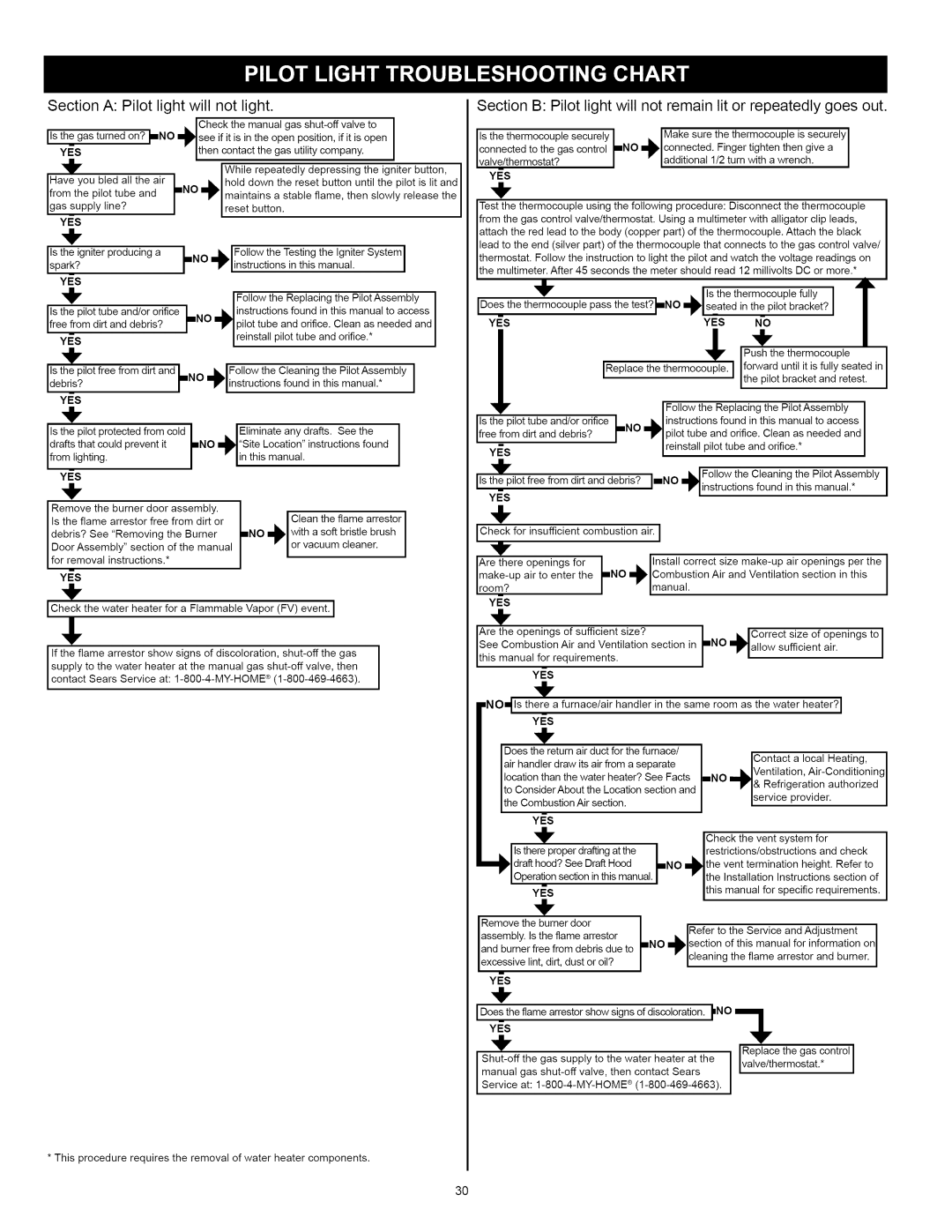
Section A: Pilot light will not light.

ICheck the manual gas shut-oft valve to I

Disthe gas turned on? I_NO mplsee if it is in the open position, if it is open I

YES


" Ithen contact the gas utility company.


IWhile repeatedly depressing the igniter button,

Have you bled all the air

NO

•l


hold

down the reset

button until the pilot is lit and


. .


from the pilot tube and

Im


mPl'Imaintains

a stable flame, then

slowly

release

the

gas supp y

ne?


/


Ireset

button.


YES


+


Is the igniter

producing

a


/

NO

ILIFollow


the Testing

the Igniter

System

l


....


I


spark?


_


_1

'nstruct'ons'nth'smanua'


YES


I Follow

the Replacing

the Pilot Assembly

I

Is the pilot

tube and/or

orifice


/


l instructions found

in this manual to access

I

free from

d rt and debr s?


_NO

_

pilot tube

and orifice. Clean as needed and


YES


--


i

re nsta

p

ot tube

and or f ce.*


÷


Is the pilot free from dirt and iiNO


Jk

Follow the Cleaning

the Pilot Assembly

I


debt s?


F


-iv

instructions

found in this manual,*

I


YES


+


Is the

pilot protected from

cold


klEliminate


any

drafts.

See the


drafts

that could prevent it


rNO

_"Site

Location"

instructions found


from

ghtng.


-Bin

this manual.


Section B: Pilot light will not remain lit or repeatedly goes out.

Is the thermocouple securely


I Make sure

the thermoceuple

is securely

I

connected to the gas control

_NO

mml,lcennected. Finger tighten then give a

I

Ivalve/therm°stat?

/

--ladditional

1/2 turn with a wrench.


I

YES


,,!,,


Test the thermocouple using the following procedure: Disconnect the thermocouple

from the gas control valve/thermostat. Using a multimeter with alligator clip leads,

attach the red lead to the body (copper part) of the thermocouple. Attach the black

lead to the end (silver part) of the thermocouple that connects to the gas control valve/

thermostat. Follow the instruction to light the pilot and watch the voltage readings on

the multimeter. After 45 seconds the meter should read 12 millivolts DC or more.*

_k


•lls

the thermoceuple

fully

I


IDoesthe thermocouple

pass

the test?_NO.plseated


in the pilot bracket?

I


YES


YES


NO


IReplace

the thermocouple.

I

forward until

it is fully seated


the pilot bracket and retest.


_r


Push the thermocouple

in


I Follow the Replacing the Pilot Assembly


Is the pilot tube and/or

orifice

/ NO

l instructions found

in this manual to access

Ifree_from dirt and debris?

_

_

pilot tube

and orifice. Clean as needed and

-


--

reinstall pilot

tube

and orifice.*


YES


÷


YES

Remove the burner door assembly.

Is the flame arrestor free from dirt or

Clean the flame arrestor with a soft bristle brush

Iisthe pilot free from dirt and debris?

I'iNO ihl• IFollow the Cleaning the Pilot Assembly

I

_

qr'linstructions found in this manual.*

I

YES

/


,I,


debris? See "Removing the Burner

or vacuum cleaner.

Door Assembly" section of the manual lfor removal instructions.*

YES

ICheck the water heater for a Flammable Vapor (FV) event. I

!,

If the flame arrestor show

signs of discoloration, shut-off the gas

I

I supply to the water heater at the manual gas shut-off valve, then

I

I contact Sears Service at:

1-800-4-MY-HOME _ (1-800-469-4663).

* This procedure requires the removal of water heater components.

lCheck for insufficient combustion air. I


Are there

openings

for

l

IInstall

correct size make-up

air

openings

per

the

I

make-up

air to enter

the

_NO

_lCombustion

Air

and Ventilation

section in this


I

room?


J


imanual.


YES


+


Are the openings

of sufficient

size?


i

iCorrect size

of

openings

to 1

thisSeemanualC°mbusti°nforrequirementsandVentilation.Air

section

in

rNO

mplallo w


sufficient

air.


l


YES


÷


=NO, Is there a furnace/air handler in the same room as the water heater? I


YES


÷


Does the return air duct for the furnace/


IContact a local


I

air handler draw its air from a separate


Heating,


location than the water heater?

See Facts

iNO


.

'.


.


IVentilation

Air-Conditioningl


to ConsiderAbout the Location

section and


_1

& Refngeratlon


authorized

I

the Combustion

Air section.


service


provider.


I


YES


Check the vent system for


IIs there proper drafting at the

/


Irestrictions/obstructions


and

check


draff hood? See Draft Hood

_NO

mml_the vent

termination

height. Refer to


IOperation

section in this manual.

tithe

Installation

Instructions

section

of


YES


this

manual for specific

requirements.


Remove

the burner door


.

iRefer to the

Service

and Adjustment

I


assembly. Is the flame arrestor


=NO m_!,section of this manual for information on I


and burner free from debris due to


excessive lint, dirt, dust or oil?


--cleaning

the flame

arrestor

and burner.

I


YES


Y_S


i Does the flame arrestor show signs of discoloration. _NO


Shut-off

the gas

supply

to the water heater

at the


va ve/thermostat.*


manual gas shut-off valve, then contact Sears


i Service

at: 1-800-4-MY-HOME

® (1-800-469-4663).

1

Replace


the gas

control


3O

Page 30
Image 30
Kenmore 153.330632, 153.330652, 153.33062, 153.330642 owner manual Section a Pilot light will not light, Ivalve/thermstat?

153.330642, 153.33062, 153.330632, 153.330652 specifications

The Kenmore model series 153.330632, 153.330652, 153.33062, and 153.330642 represent a versatile lineup of washing machines designed to cater to a variety of laundry needs. Each model comes equipped with unique features and technologies aimed at enhancing the user's washing experience while ensuring reliability and performance.

One of the standout features across these models is their efficient water usage. Designed with modern technology, these machines incorporate advanced sensors that adjust the water level according to the load size. This not only conserves water but also contributes to lower utility bills, making them environmentally friendly options.

In terms of operation, the Kenmore models boast a range of wash cycles tailored to different fabric types and soil levels. From delicate items to heavy-duty fabrics, users can choose the appropriate cycle to ensure optimal cleaning without damaging their garments. The presence of a quick wash option is also a highlight, enabling users to clean lightly soiled items in a fraction of the time.

The Kenmore series is also designed for user convenience. Features such as a digital display control panel allow for intuitive operation. Users can easily select their desired settings and monitor the wash cycle progress. Additionally, the machines are equipped with a delay start function, which provides flexibility for users to schedule their laundry according to their convenience.

Another notable characteristic of these models is the installation of noise-reducing technologies. This minimizes operational sounds, allowing for quieter washing cycles, which is particularly beneficial for households with infants or those who prefer a tranquil environment.

Durability is a significant aspect of the Kenmore brand. Each machine in this series is constructed with high-quality materials designed to withstand the rigors of regular use. The stainless-steel tubs are resistant to chipping and snagging, ensuring that they maintain their efficiency over long periods.

In summary, the Kenmore models 153.330632, 153.330652, 153.33062, and 153.330642 are packed with features aimed at improving the laundry experience. With efficient water usage, versatile wash cycles, user-friendly controls, noise reduction technologies, and durable construction, these machines stand out as reliable choices for modern households seeking an effective laundry solution. As users navigate their laundry tasks, these washing machines promise to deliver performance while keeping convenience and sustainability at the forefront.