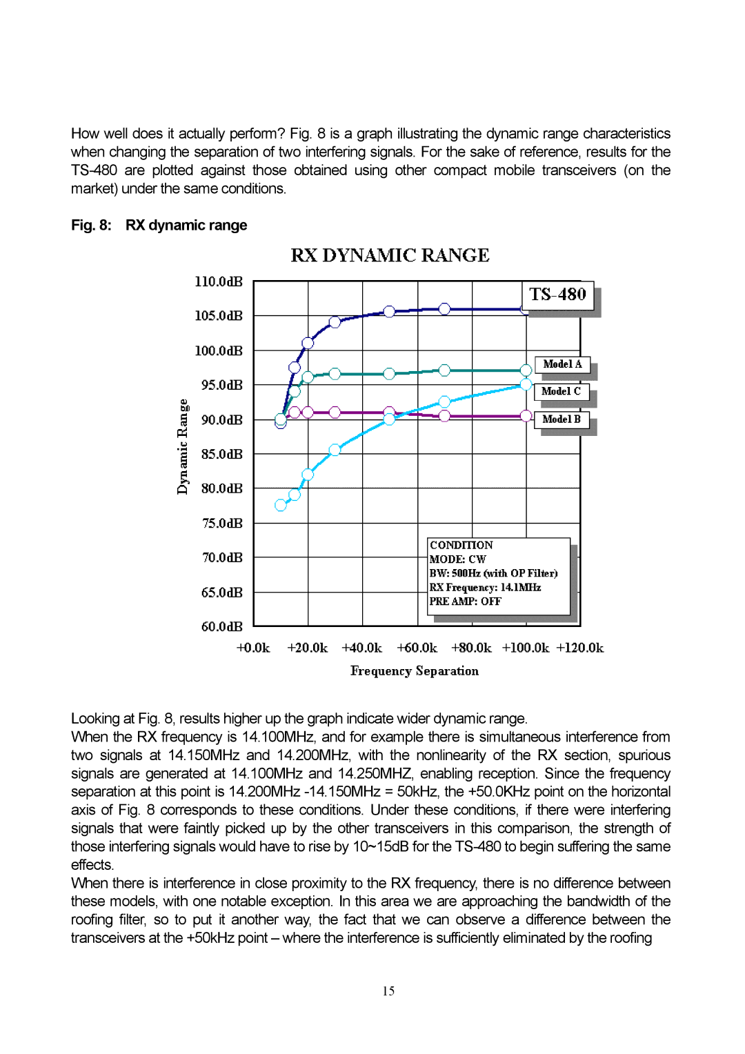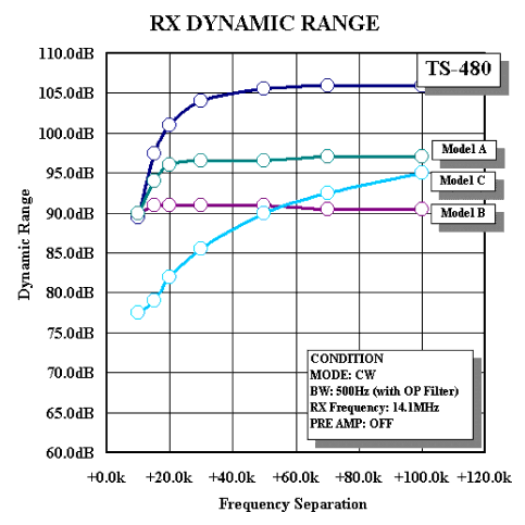
How well does it actually perform? Fig. 8 is a graph illustrating the dynamic range characteristics when changing the separation of two interfering signals. For the sake of reference, results for the
Fig. 8: RX dynamic range
Looking at Fig. 8, results higher up the graph indicate wider dynamic range.
When the RX frequency is 14.100MHz, and for example there is simultaneous interference from two signals at 14.150MHz and 14.200MHz, with the nonlinearity of the RX section, spurious signals are generated at 14.100MHz and 14.250MHZ, enabling reception. Since the frequency separation at this point is 14.200MHz
When there is interference in close proximity to the RX frequency, there is no difference between these models, with one notable exception. In this area we are approaching the bandwidth of the roofing filter, so to put it another way, the fact that we can observe a difference between the transceivers at the +50kHz point – where the interference is sufficiently eliminated by the roofing
15