| B |
|
| D |
| C |
|
|
|
A |
| E |
|
|
|
|
|
| |
F |
| J | I | G |
|
| |||
| K |
|
| |
| L |
|
| |
|
|
|
| |
|
|
|
| H |
8½" | L |
(21.6 cm) |
|
14"
*** (35.6 cm)
1½" | 2¼" (5.7 cm) |
(3.8 cm) | |
| 1¼"* |
| (3.1 cm) |
| 8½" (21.6 cm)** |
| gas line location |
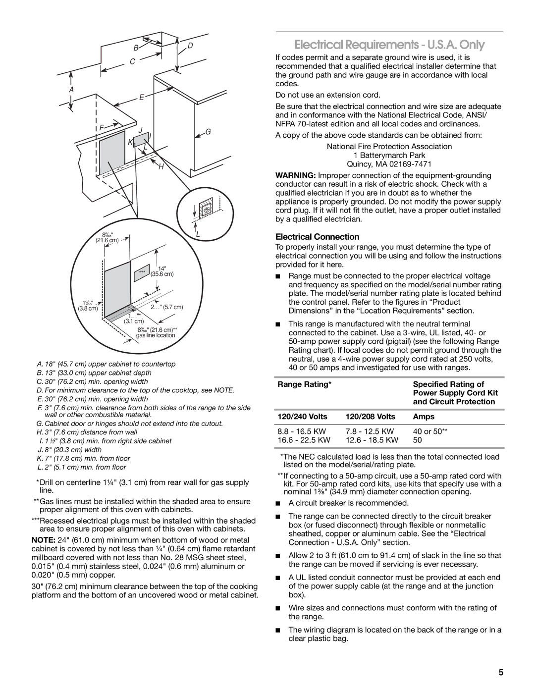
A. 18" (45.7 cm) upper cabinet to countertop B. 13" (33.0 cm) upper cabinet depth
C. 30" (76.2 cm) min. opening width
D. For minimum clearance to the top of the cooktop, see NOTE. E. 30" (76.2 cm) min. opening width
F. 3" (7.6 cm) min. clearance from both sides of the range to the side wall or other combustible material.
G. Cabinet door or hinges should not extend into the cutout. H. 3" (7.6 cm) distance from wall
I. 1¹⁄₂" (3.8 cm) min. from right side cabinet J. 8" (20.3 cm) width
K. 7" (17.8 cm) min. from floor L. 2" (5.1 cm) min. from floor
*Drill on centerline 1¼" (3.1 cm) from rear wall for gas supply line.
**Gas lines must be installed within the shaded area to ensure proper alignment of this oven with cabinets.
***Recessed electrical plugs must be installed within the shaded area to ensure proper alignment of this oven with cabinets.
NOTE: 24" (61.0 cm) minimum when bottom of wood or metal cabinet is covered by not less than ¹⁄₄" (0.64 cm) flame retardant millboard covered with not less than No. 28 MSG sheet steel, 0.015" (0.4 mm) stainless steel, 0.024" (0.6 mm) aluminum or 0.020" (0.5 mm) copper.
30" (76.2 cm) minimum clearance between the top of the cooking platform and the bottom of an uncovered wood or metal cabinet.
Electrical Requirements - U.S.A. Only
If codes permit and a separate ground wire is used, it is recommended that a qualified electrical installer determine that the ground path and wire gauge are in accordance with local codes.
Do not use an extension cord.
Be sure that the electrical connection and wire size are adequate and in conformance with the National Electrical Code, ANSI/ NFPA
A copy of the above code standards can be obtained from:
National Fire Protection Association
1 Batterymarch Park
Quincy, MA
WARNING: Improper connection of the
Electrical Connection
To properly install your range, you must determine the type of electrical connection you will be using and follow the instructions provided for it here.
■Range must be connected to the proper electrical voltage and frequency as specified on the model/serial number rating plate. The model/serial number rating plate is located behind the control panel. Refer to the figures in “Product Dimensions” in the “Location Requirements” section.
■This range is manufactured with the neutral terminal connected to the cabinet. Use a
Range Rating* |
| Specified Rating of |
|
| Power Supply Cord Kit |
|
| and Circuit Protection |
|
|
|
120/240 Volts | 120/208 Volts | Amps |
|
|
|
8.8 - 16.5 KW | 7.8 - 12.5 KW | 40 or 50** |
16.6 - 22.5 KW | 12.6 - 18.5 KW | 50 |
|
|
|
*The NEC calculated load is less than the total connected load listed on the model/serial/rating plate.
**If connecting to a
■A circuit breaker is recommended.
■The range can be connected directly to the circuit breaker box (or fused disconnect) through flexible or nonmetallic sheathed, copper or aluminum cable. See the “Electrical Connection - U.S.A. Only” section.
■Allow 2 to 3 ft (61.0 cm to 91.4 cm) of slack in the line so that the range can be moved if servicing is ever necessary.
■A UL listed conduit connector must be provided at each end of the power supply cable (at the range and at the junction box).
■Wire sizes and connections must conform with the rating of the range.
■The wiring diagram is located on the back of the range or in a clear plastic bag.
5