Operation
jTighten the stop screw 9 for depth stop 10 again.
jRelease the clamping lever 15 by turning it clockwise and then guide the device back up again. Check the depth of cut by carrying out a further practical test.
Setting the depth of cut using the step buffer
You can use the step buffer 7 to make greater depths of cut in several successive stages in which less material is removed.
jSet the required depth of cut with the lowest step of the step buffer 7 (as described above).
jAfterwards the higher steps can be used for the first few cuts.
jLock the device by turning the clamping lever 15 anticlockwise.
jCarry out the routing process using uniform speed and pressure
jStop the routing process by lifting the device from the workpiece and switching it off.
QSetting the guide bushing
jInsert the guide bushing 35 from below into the guide plate 6 .
jFasten the guide bushing 35 to the base plate
5using the two screws 30 of the vacuum ex- traction adapter. Make sure that the guide bushing 35 is the right way round - the guide bushing ring 36 must be facing downwards.
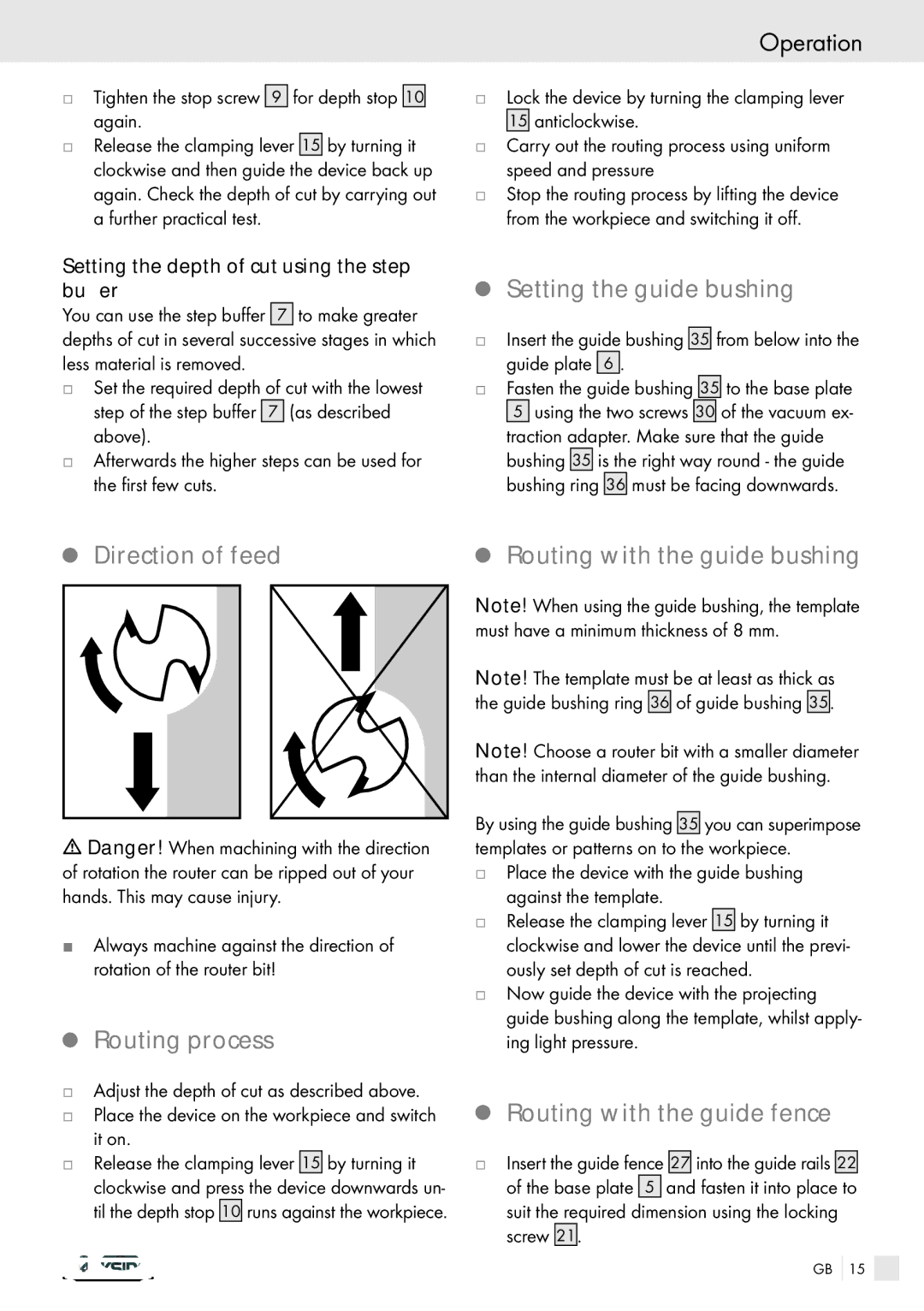
Q Direction of feed | Q Routing with the guide bushing |
mDanger! When machining with the direction of rotation the router can be ripped out of your hands. This may cause injury.
JAlways machine against the direction of rotation of the router bit!
QRouting process
jAdjust the depth of cut as described above.
jPlace the device on the workpiece and switch it on.
jRelease the clamping lever 15 by turning it clockwise and press the device downwards un- til the depth stop 10 runs against the workpiece.
Note! When using the guide bushing, the template must have a minimum thickness of 8 mm.
Note! The template must be at least as thick as the guide bushing ring 36 of guide bushing 35.
Note! Choose a router bit with a smaller diameter than the internal diameter of the guide bushing.
By using the guide bushing 35 you can superimpose templates or patterns on to the workpiece.
jPlace the device with the guide bushing against the template.
jRelease the clamping lever 15 by turning it clockwise and lower the device until the previ- ously set depth of cut is reached.
jNow guide the device with the projecting guide bushing along the template, whilst apply- ing light pressure.
QRouting with the guide fence
jInsert the guide fence 27 into the guide rails 22 of the base plate 5 and fasten it into place to suit the required dimension using the locking screw 21.
GB 15