Table of Contents
Section 2: Optional Equipment
Front Guards
!DANGER
Rotary Cutters have the ability to discharge objects at high speeds. Use front and rear safety guards when cutting along highways or in an area where people may be present.
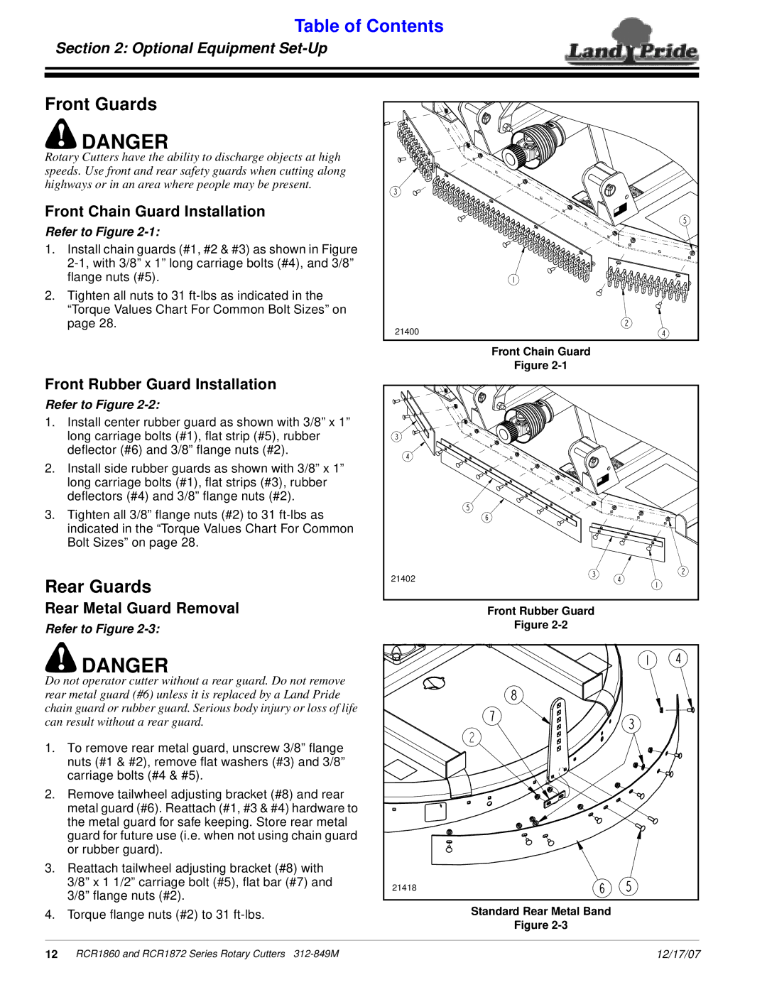
Front Chain Guard Installation
Refer to Figure 2-1:
1.Install chain guards (#1, #2 & #3) as shown in Figure
2.Tighten all nuts to 31
21400 |
| Front Chain Guard |
| Figure |
Front Rubber Guard Installation |
|
Refer to Figure |
|
1. Install center rubber guard as shown with 3/8” x 1” |
|
long carriage bolts (#1), flat strip (#5), rubber |
|
deflector (#6) and 3/8” flange nuts (#2). |
|
2. Install side rubber guards as shown with 3/8” x 1” |
|
long carriage bolts (#1), flat strips (#3), rubber |
|
deflectors (#4) and 3/8” flange nuts (#2). |
|
3. Tighten all 3/8” flange nuts (#2) to 31 |
|
indicated in the “Torque Values Chart For Common |
|
Bolt Sizes” on page 28. |
|
Rear Guards | 21402 |
|
Rear Metal Guard Removal | Front Rubber Guard |
Refer to Figure | Figure |
!DANGER
Do not operator cutter without a rear guard. Do not remove rear metal guard (#6) unless it is replaced by a Land Pride chain guard or rubber guard. Serious body injury or loss of life can result without a rear guard.
1.To remove rear metal guard, unscrew 3/8” flange nuts (#1 & #2), remove flat washers (#3) and 3/8” carriage bolts (#4 & #5).
2.Remove tailwheel adjusting bracket (#8) and rear metal guard (#6). Reattach (#1, #3 & #4) hardware to the metal guard for safe keeping. Store rear metal guard for future use (i.e. when not using chain guard or rubber guard).
3.Reattach tailwheel adjusting bracket (#8) with 3/8” x 1 1/2” carriage bolt (#5), flat bar (#7) and 3/8” flange nuts (#2).
4.Torque flange nuts (#2) to 31
21418 |
Standard Rear Metal Band
Figure
12 RCR1860 and RCR1872 Series Rotary Cutters | 12/17/07 |