CARE AND OPERATI0N
ASH DRAWER
The large ash drawer located on the left side of the ped- estal is designed to make cleaning easier by containing the ashes in a removable drawer.
Ash
Drawer
WARNING: DO NOT OPERATE THIS STOVE WITHOUT THE ASH DRAWER PROPERLY INSTALLED AND SE- CURED (SEALED), AS THIS WILL PRODUCE EX- TREME TEMPERATURES, RESULTING IN OVERFIR- ING. THE ASH DRAWER GASKET PROVIDES AN IM- PORTANT SEAL, AND MUST BE MAINTAINED (SEE MAINTENANCE REQUIREMENTS ON PAGE 19). OVERFIRING CAN RESULT IN DAMAGE TO THE AP- PLIANCE OR A HOUSE FIRE. OPERATION WITH THE ASH DRAWER OPEN OR AJAR, NULLIFIES THE SAFETY LISTING AND VOIDS THE WARRANTY.
CATALYTIC COMBUSTOR
How it works: From 5 to 30 percent of the chemical en- ergy contained in every log escapes up the chimney when wood is burned in a conventional stove. The cata- lytic combustor is designed to make use of this energy, converting it into useful heat as it lessens chimney creo- sote
CATALYTIC BYPASS DAMPER CONTROL
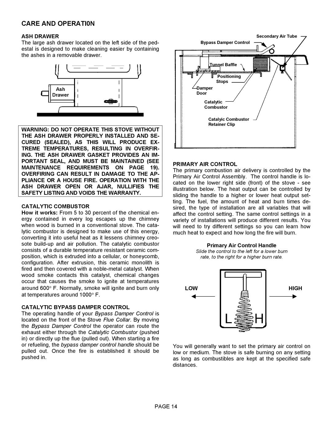
The operating handle of your Bypass Damper Control is located on the front of the Stove Flue Collar. By moving the Bypass Damper Control the operator can route the exhaust either through the Catalytic Combustor (pushed in) or directly up the flue (pulled out). When starting a fire or refueling, the bypass damper control handle should be pulled out. Once the fire is established it should be pushed in.
Secondary Air Tube
Bypass Damper Control
Tunnel Baffle
Positioning
Stops
Damper
Door
Catalytic
Combustor
Catalyic Combustor
Retainer Clip
PRIMARY AIR CONTROL
The primary combustion air delivery is controlled by the Primary Air Control Assembly. The control handle is lo- cated on the lower right side (front) of the stove - see illustration below. The heat output can be controlled by sliding the handle to a higher or lower heat output set- ting. The fuel, the amount of heat and burn times de- sired, the type of installation are all variables that will affect the control setting. The same control settings in a variety of installations will produce different results. You will need to try different settings so you can learn how much heat to expect and how long the fire will burn.
Primary Air Control Handle
Slide the control to the left for a lower burn
rate, to the right for a higher burn rate.
LOW |
| HIGH | ||
|
|
|
|
|
You will generally want to set the primary air control on low or medium. The stove is safe burning on any setting as long as combustibles are kept at the specified safe distances.
PAGE 14
