INSTALLATION
See Pipe Manufacturers Instructions For Installation Requirements Of Venting Components And Vent Clearances.
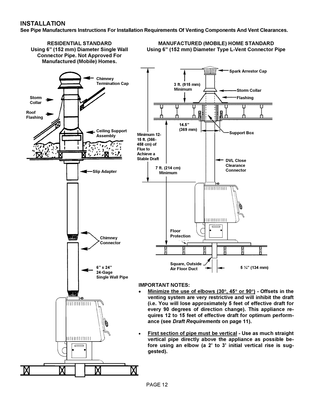
RESIDENTIAL STANDARD
Using 6” (152 mm) Diameter Single Wall
Connector Pipe. Not Approved For
Manufactured (Mobile) Homes.
Chimney
Termination Cap
Storm
Collar
Roof
Flashing
Ceiling Support
Assembly
Slip Adapter
Chimney
Connector
6” x 24”
Single Wall Pipe
MANUFACTURED (MOBILE) HOME STANDARD
Using 6” (152 mm) Diameter Type L-Vent Connector Pipe
| Spark Arrestor Cap | ||
3 ft. (915 mm) |
|
|
|
|
|
| |
Minimum |
|
|
|
| Storm Collar | ||
|
|
|
|
|
| Flashing | |
|
| 14.5” |
|
|
| ||
|
| (369 mm) |
|
|
| ||
|
| Support Box | |||||
Minimum 12- |
|
| |||||
15 ft. (366- |
|
|
|
| |||
|
|
| |||||
458 cm) of |
|
|
|
| |||
Flue to |
|
|
|
| |||
Achieve a |
|
|
|
| |||
Stable Draft |
|
|
|
| |||
DVL Close | |||||||
|
| ||||||
|
|
|
| Clearance |
| ||
| 7 ft. (214 cm) |
| |||||
|
| Connector |
| ||||
| Minimum |
|
| ||||
|
|
|
|
| |||
|
|
|
|
|
|
| |
Floor
Protection
Square, Outside | 5 ¼” (134 mm) |
Air Floor Duct |
IMPORTANT NOTES:
•Minimize the use of elbows (30°, 45° or 90°) - Offsets in the venting system are very restrictive and will inhibit the draft (i.e. You will lose approximately 5 feet of effective draft for every 90 degrees of direction change). This appliance re- quires 12 to 15 feet of effective draft for optimum perform- ance (see Draft Requirements on page 11).
•First section of pipe must be vertical - Use as much straight vertical pipe directly above the appliance as possible be- fore using an elbow (a 2’ to 3’ initial vertical rise is sug- gested).
PAGE 12