PLANNING YOUR INSTALLATION
ALCOVE CLEARANCES
NOTE:" = inches, mm = millimeter, cm = centimeter Alcoves must have minimum dimensions of 84" (214 cm) height, 56" (142 cm) width and 24" (610 mm) maximum depth.
Require pipe: Type L Vent pipe to the top of the stove. Manufactured (mobile) home installations must be equipped with a rain cap and spark arrestor and must use a pipe shield extending a minimum of 24" (610 mm) above the stove (resting on stove) is mandatory for the installation of this appliance into a combustible alcove.
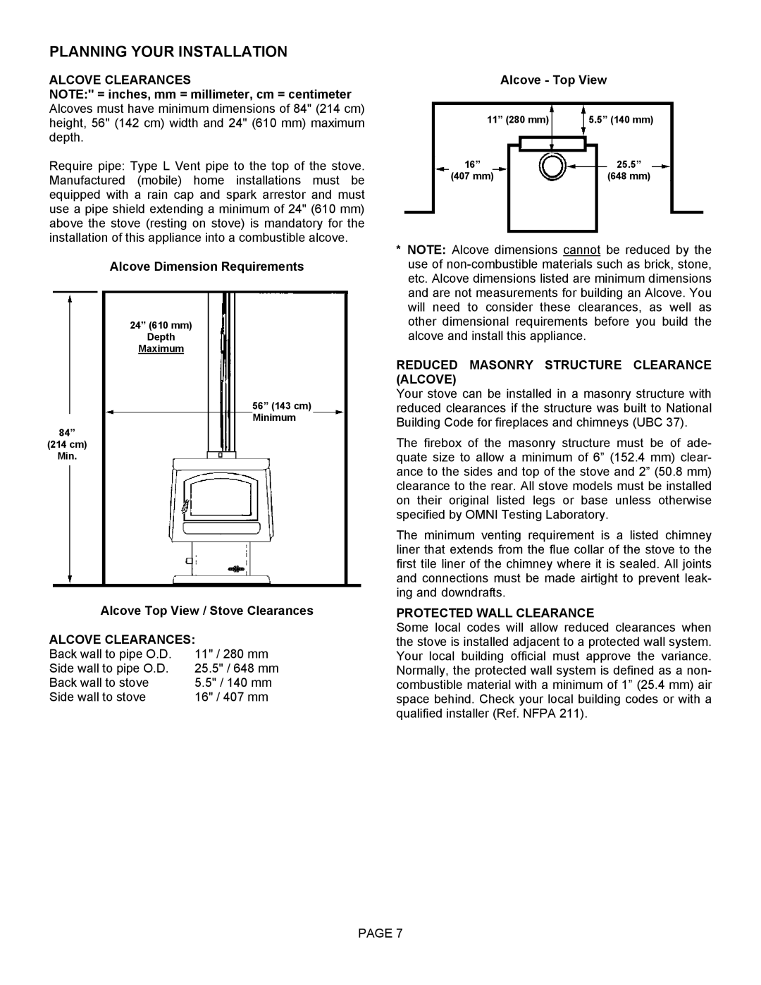
Alcove Dimension Requirements
24” (610 mm)
Depth
Maximum
56” (143 cm) Minimum
84”
(214 cm)
Min.
Alcove Top View / Stove Clearances
ALCOVE CLEARANCES:
Back wall to pipe O.D. | 11" / 280 mm |
Side wall to pipe O.D. | 25.5" / 648 mm |
Back wall to stove | 5.5" / 140 mm |
Side wall to stove | 16" / 407 mm |
Alcove - Top View
11” (280 mm) | 5.5” (140 mm) |
16” | 25.5” |
(407 mm) | (648 mm) |
*NOTE: Alcove dimensions cannot be reduced by the use of
REDUCED MASONRY STRUCTURE CLEARANCE (ALCOVE)
Your stove can be installed in a masonry structure with reduced clearances if the structure was built to National Building Code for fireplaces and chimneys (UBC 37).
The firebox of the masonry structure must be of ade- quate size to allow a minimum of 6” (152.4 mm) clear- ance to the sides and top of the stove and 2” (50.8 mm) clearance to the rear. All stove models must be installed on their original listed legs or base unless otherwise specified by OMNI Testing Laboratory.
The minimum venting requirement is a listed chimney liner that extends from the flue collar of the stove to the first tile liner of the chimney where it is sealed. All joints and connections must be made airtight to prevent leak- ing and downdrafts.
PROTECTED WALL CLEARANCE
Some local codes will allow reduced clearances when the stove is installed adjacent to a protected wall system. Your local building official must approve the variance. Normally, the protected wall system is defined as a non- combustible material with a minimum of 1” (25.4 mm) air space behind. Check your local building codes or with a qualified installer (Ref. NFPA 211).
PAGE 7