INSTALLATION - Combustible Wall Chimney Connector
A
Min. 12 in. (304.8mm)
to Combustibles
Min. Chimney Clearance to Brick & Combustibles – 2 in. (50.8mm)
| Min. Clearance 12 in. |
Flue | (304.8mm) of Brick |
| |
Chimney | Chimney |
| Connector |
| Fire Clay |
| Liner |
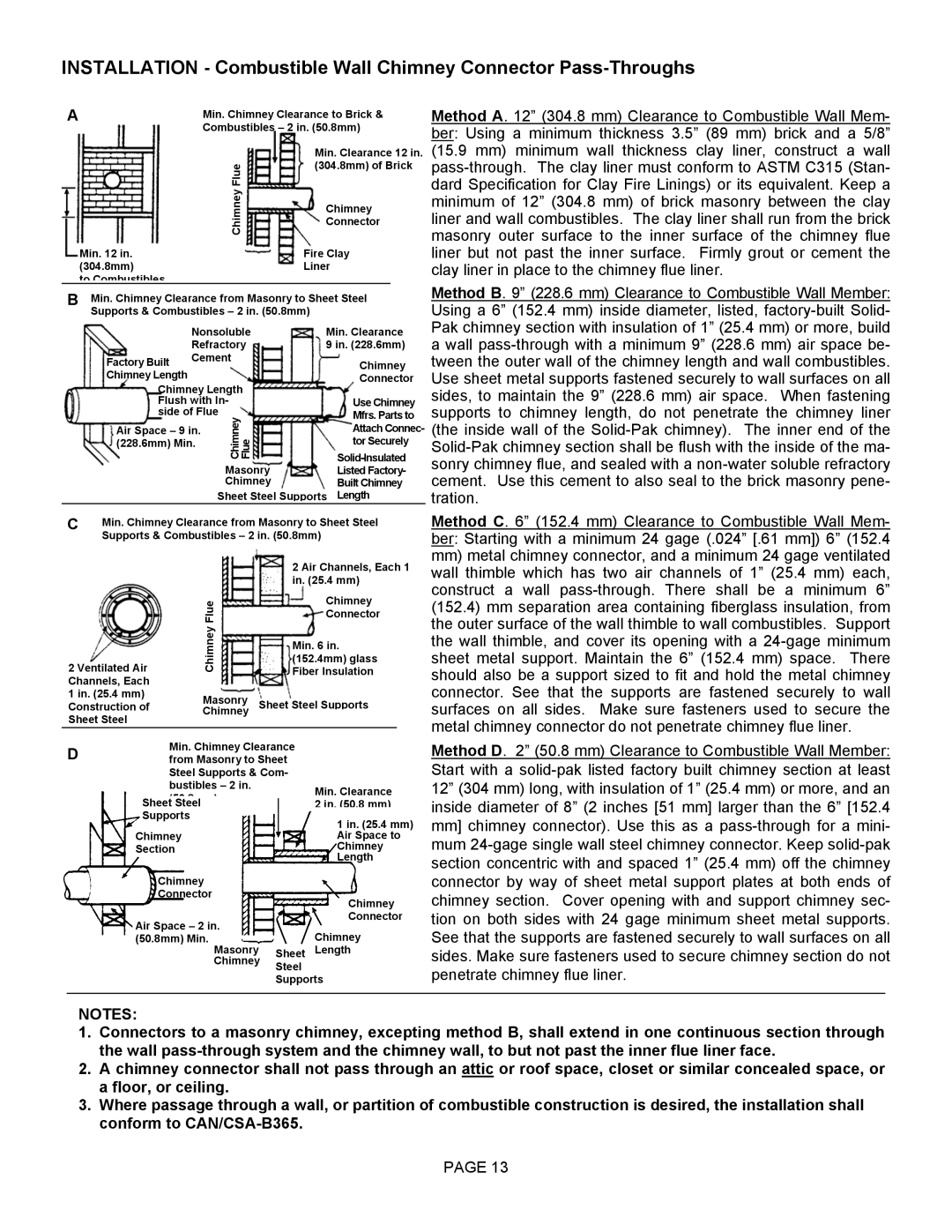
Method A. 12” (304.8 mm) Clearance to Combustible Wall Mem- ber: Using a minimum thickness 3.5” (89 mm) brick and a 5/8” (15.9 mm) minimum wall thickness clay liner, construct a wall
| B | Min. Chimney Clearance from Masonry to Sheet Steel |
| Method B. 9” (228.6 mm) Clearance to Combustible Wall Member: | |||
| Using a 6” (152.4 mm) inside diameter, listed, | ||||||
|
| Supports & Combustibles – 2 in. (50.8mm) |
|
| |||
|
|
| Nonsoluble | Min. Clearance | Pak chimney section with insulation of 1” (25.4 mm) or more, build | ||
|
|
| Refractory | 9 in. (228.6mm) | a wall | ||
|
| Factory Built | Cement | Chimney | tween the outer wall of the chimney length and wall combustibles. | ||
|
| Chimney Length |
|
| Connector | Use sheet metal supports fastened securely to wall surfaces on all | |
|
| Chimney Length |
|
| sides, to maintain the 9” (228.6 mm) air space. When fastening | ||
|
| Flush with In- | Use Chimney | ||||
|
| side of Flue | Mfrs. Parts to | supports to chimney length, do not penetrate the chimney liner | |||
|
| Air Space – 9 in. | Chimney Flue | Attach Connec- | (the inside wall of the | ||
|
| (228.6mm) Min. |
| tor Securely | |||
|
|
| |||||
|
|
|
| Masonry | sonry chimney flue, and sealed with a | ||
|
|
|
| Listed Factory- | cement. Use this cement to also seal to the brick masonry pene- | ||
|
|
|
| Chimney | Built Chimney | ||
|
|
|
| Sheet Steel Supports Length | tration. | ||
| C | Min. Chimney Clearance from Masonry to Sheet Steel | |||
|
| Supports & Combustibles – 2 in. (50.8mm) | |||
|
|
|
| 2 Air Channels, Each 1 | |
|
|
|
| in. (25.4 mm) | |
|
|
| Flue | Chimney | |
|
|
| Connector | ||
|
|
| Chimney | ||
| 2 Ventilated Air | Fiber Insulation | |||
|
|
|
| Min. 6 in. | |
|
|
|
| (152.4mm) glass | |
| Channels, Each |
|
|
| |
| 1 in. (25.4 mm) | Masonry | Sheet Steel Supports | ||
| Construction of | ||||
| Sheet Steel | Chimney |
|
| |
|
|
|
| ||
|
|
| Min. Chimney Clearance | ||
| D |
| |||
|
| from Masonry to Sheet | |||
|
|
| Steel Supports & Com- | ||
|
|
| |||
|
|
| bustibles – 2 in. | Min. Clearance | |
|
|
| (50 8 ) | ||
|
| Sheet Steel | 2 in. (50.8 mm) | ||
|
| Supports | 1 in. (25.4 mm) | ||
|
| Chimney | |||
|
| Air Space to | |||
|
| Section | Chimney | ||
|
|
|
| Length | |
Chimney
Connector
Chimney
Method C. 6” (152.4 mm) Clearance to Combustible Wall Mem- ber: Starting with a minimum 24 gage (.024” [.61 mm]) 6” (152.4
mm)metal chimney connector, and a minimum 24 gage ventilated wall thimble which has two air channels of 1” (25.4 mm) each, construct a wall
Method D. 2” (50.8 mm) Clearance to Combustible Wall Member:
Start with a
Air Space – 2 in.
Connector
tion on both sides with 24 gage minimum sheet metal supports.
(50.8mm) Min.Chimney
Masonry Sheet Length
Chimney Steel
Supports
See that the supports are fastened securely to wall surfaces on all sides. Make sure fasteners used to secure chimney section do not penetrate chimney flue liner.
NOTES:
1.Connectors to a masonry chimney, excepting method B, shall extend in one continuous section through the wall
2.A chimney connector shall not pass through an attic or roof space, closet or similar concealed space, or a floor, or ceiling.
3.Where passage through a wall, or partition of combustible construction is desired, the installation shall conform to
PAGE 13