Introduction
Connection Options
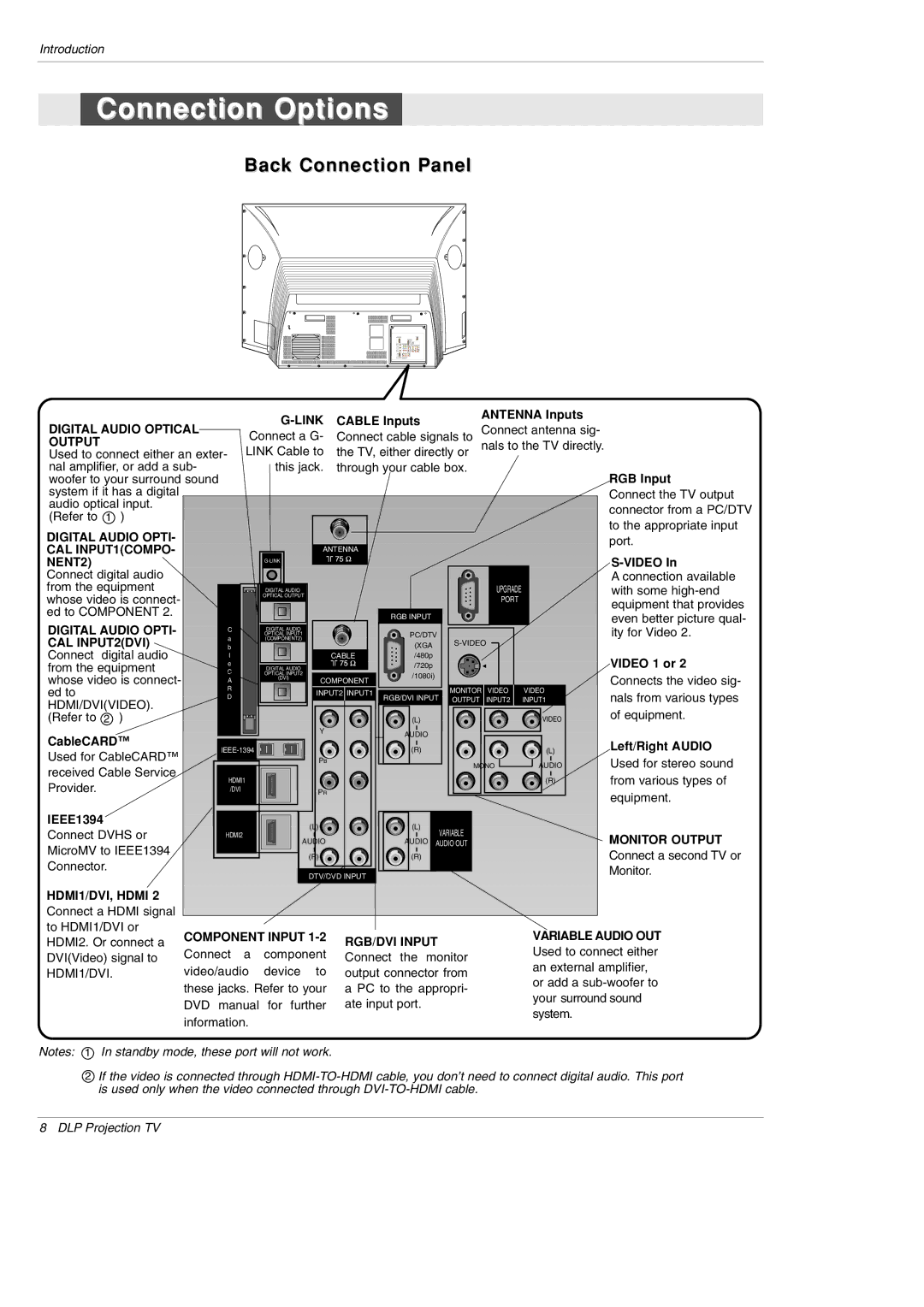
Back Connection Panel
|
|
| CABLE Inputs |
| ANTENNA Inputs |
| ||||
DIGITAL AUDIO OPTICAL |
|
| Connect antenna sig- |
| ||||||
Connect a G- | Connect cable signals to |
| ||||||||
OUTPUT |
| LINK Cable to | the TV, either directly or | nals to the TV directly. |
| |||||
Used to connect either an exter- |
| |||||||||
|
|
| ||||||||
nal amplifier, or add a sub- |
| this jack. | through your cable box. |
|
| RGB Input | ||||
woofer to your surround sound |
|
|
|
|
|
|
|
| ||
system if it has a digital |
|
|
|
|
|
|
|
|
| Connect the TV output |
audio optical input. |
|
|
|
|
|
|
|
|
| connector from a PC/DTV |
(Refer to 1 ) |
|
|
|
|
|
|
|
|
| |
|
|
|
|
|
|
|
|
| to the appropriate input | |
DIGITAL AUDIO OPTI- |
|
|
|
|
|
|
|
|
| |
|
|
|
|
|
|
|
|
| port. | |
CAL INPUT1(COMPO- |
|
|
| ANTENNA |
|
|
|
| ||
NENT2) |
|
|
|
|
|
|
|
| ||
Connect digital audio |
|
|
|
|
|
|
|
|
| A connection available |
from the equipment |
|
| DIGITAL AUDIO |
|
|
|
| UPGRADE |
| with some |
whose video is connect- |
|
| OPTICAL OUTPUT |
|
|
|
| PORT |
| |
|
|
|
|
|
|
|
| equipment that provides | ||
ed to COMPONENT 2. |
|
|
|
|
|
|
|
|
| |
|
|
|
| RGB INPUT |
|
|
| even better picture qual- | ||
DIGITAL AUDIO OPTI- |
|
| OPTICAL INPUT1 |
|
| PC/DTV |
|
|
| |
C |
|
|
|
|
|
| ity for Video 2. | |||
|
| DIGITAL AUDIO |
|
|
|
|
|
|
| |
CAL INPUT2(DVI) | a |
| (COMPONENT2) |
|
| (XGA |
|
| ||
b |
|
|
|
|
|
| ||||
Connect digital audio | l |
|
|
| CABLE | /480p |
|
|
| VIDEO 1 or 2 |
from the equipment | e |
| OPTICAL INPUT2 |
|
| /720p |
|
|
| |
C |
|
|
|
|
|
| ||||
|
|
| DIGITAL AUDIO |
|
|
|
|
| ||
whose video is connect- | A |
| (DVI) | COMPONENT | /1080i) |
|
|
| Connects the video sig- | |
|
|
|
|
|
| |||||
ed to | R |
|
| INPUT2 INPUT1 |
| MONITOR VIDEO | VIDEO | nals from various types | ||
D |
|
|
| OUTPUT | INPUT2 | INPUT1 | ||||
HDMI/DVI(VIDEO). |
|
|
|
| RGB/DVI INPUT | |||||
|
|
|
|
|
|
|
|
| of equipment. | |
(Refer to 2 ) |
|
|
|
|
| (L) |
|
| VIDEO | |
CableCARD™ |
|
|
| Y |
| AUDIO |
|
|
|
|
|
|
|
|
|
|
|
| Left/Right AUDIO | ||
|
|
| (R) |
|
| (L) | ||||
Used for CableCARD™ |
|
|
|
|
| |||||
|
|
| PB |
|
| MONO | AUDIO | Used for stereo sound | ||
received Cable Service |
|
|
|
|
|
| ||||
HDMI1 |
|
|
|
|
|
| (R) | from various types of | ||
Provider. |
|
|
|
|
|
| ||||
/DVI |
|
| PR |
|
|
|
|
| equipment. | |
|
|
|
|
|
|
|
|
|
| |
IEEE1394 |
|
|
| (L) |
| (L) |
|
|
|
|
Connect DVHS or | HDMI2 |
|
|
| VARIABLE |
|
|
| ||
| AUDIO |
|
|
|
| MONITOR OUTPUT | ||||
MicroMV to IEEE1394 |
|
|
| AUDIO AUDIO OUT |
|
| ||||
|
|
| (R) |
| (R) |
|
|
| Connect a second TV or | |
Connector. |
|
|
|
|
|
|
| |||
|
|
| DTV/DVD INPUT |
|
|
|
| Monitor. | ||
|
|
|
|
|
|
|
| |||
|
|
|
|
|
|
|
|
| ||
HDMI1/DVI, HDMI 2 |
|
|
|
|
|
|
|
|
|
|
Connect a HDMI signal |
|
|
|
|
|
|
|
|
|
|
to HDMI1/DVI or | COMPONENT INPUT |
|
|
|
| VARIABLE AUDIO OUT | ||||
HDMI2. Or connect a | RGB/DVI INPUT |
|
| |||||||
Connect | a | component |
|
| Used to connect either | |||||
DVI(Video) signal to | Connect | the monitor |
| |||||||
HDMI1/DVI. | video/audio | device to | output connector from |
| an external amplifier, | |||||
| or add a | |||||||||
| these jacks. Refer to your | a PC to the appropri- |
| |||||||
|
| your surround sound | ||||||||
| DVD manual | for further | ate input port. |
|
| |||||
|
|
| system. |
| ||||||
| information. |
|
|
|
|
|
|
| ||
|
|
|
|
|
|
|
|
| ||
Notes: 1 In standby mode, these port will not work.
2If the video is connected through
8 DLP Projection TV