| 42 |
| LAT |
| CABLE |
82 | 55 |
69 |
|
| 11 |
| 48 |
FIGURE 25 | 90 3/8 X |
25 |
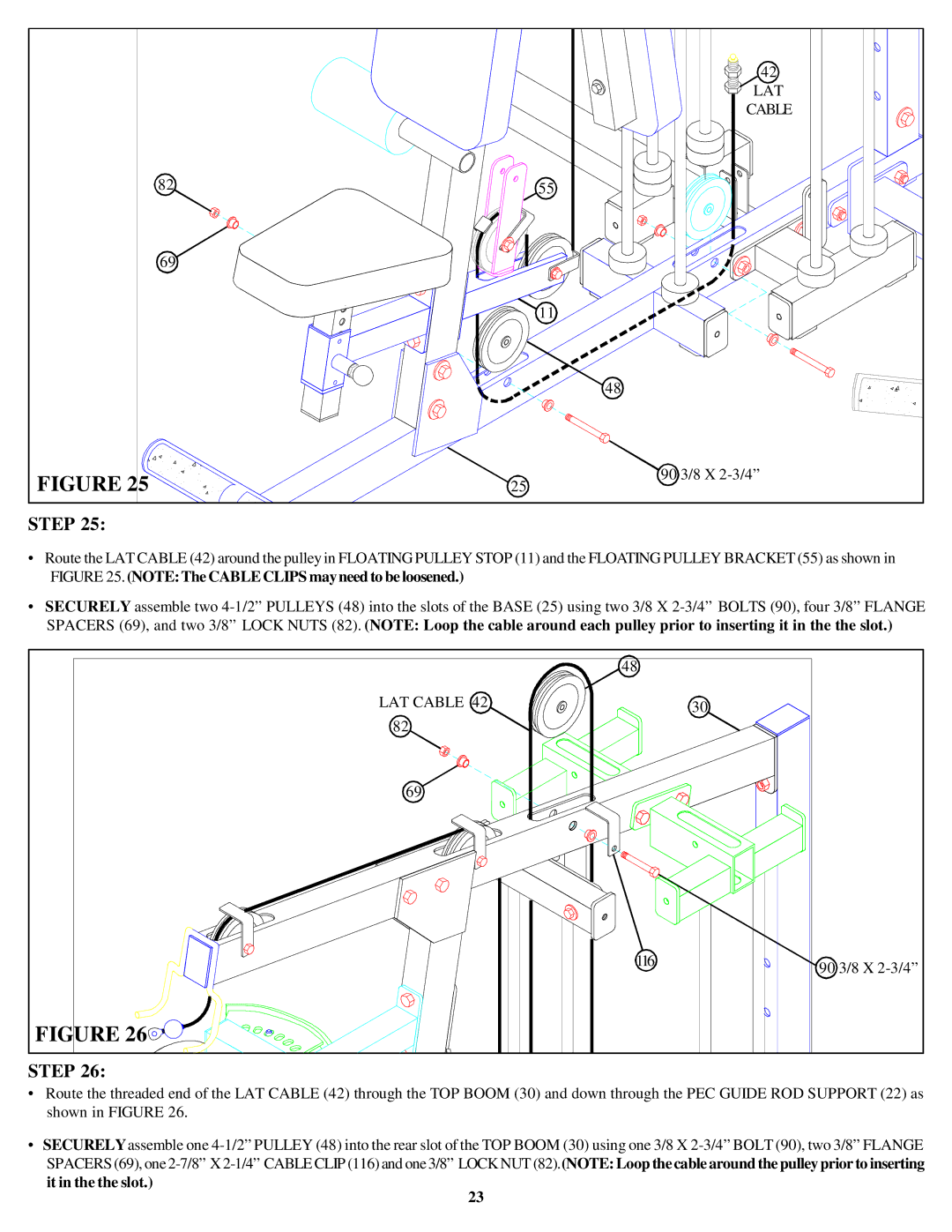
STEP 25:
•Route the LAT CABLE (42) around the pulley in FLOATING PULLEY STOP (11) and the FLOATING PULLEY BRACKET (55) as shown in FIGURE 25. (NOTE: The CABLE CLIPS may need to be loosened.)
•SECURELY assemble two
| 48 |
|
LAT CABLE 42 |
| 30 |
82 |
|
|
69 |
|
|
| 116 | 90 3/8 X |
|
| |
FIGURE 26 |
|
|
STEP 26:
•Route the threaded end of the LAT CABLE (42) through the TOP BOOM (30) and down through the PEC GUIDE ROD SUPPORT (22) as shown in FIGURE 26.
•SECURELY assemble one
it in the the slot.)
23