FIGURE 36
48 |
69 |
82 |
3/8 X |
20 |
116 |
44 PRESS CABLE |
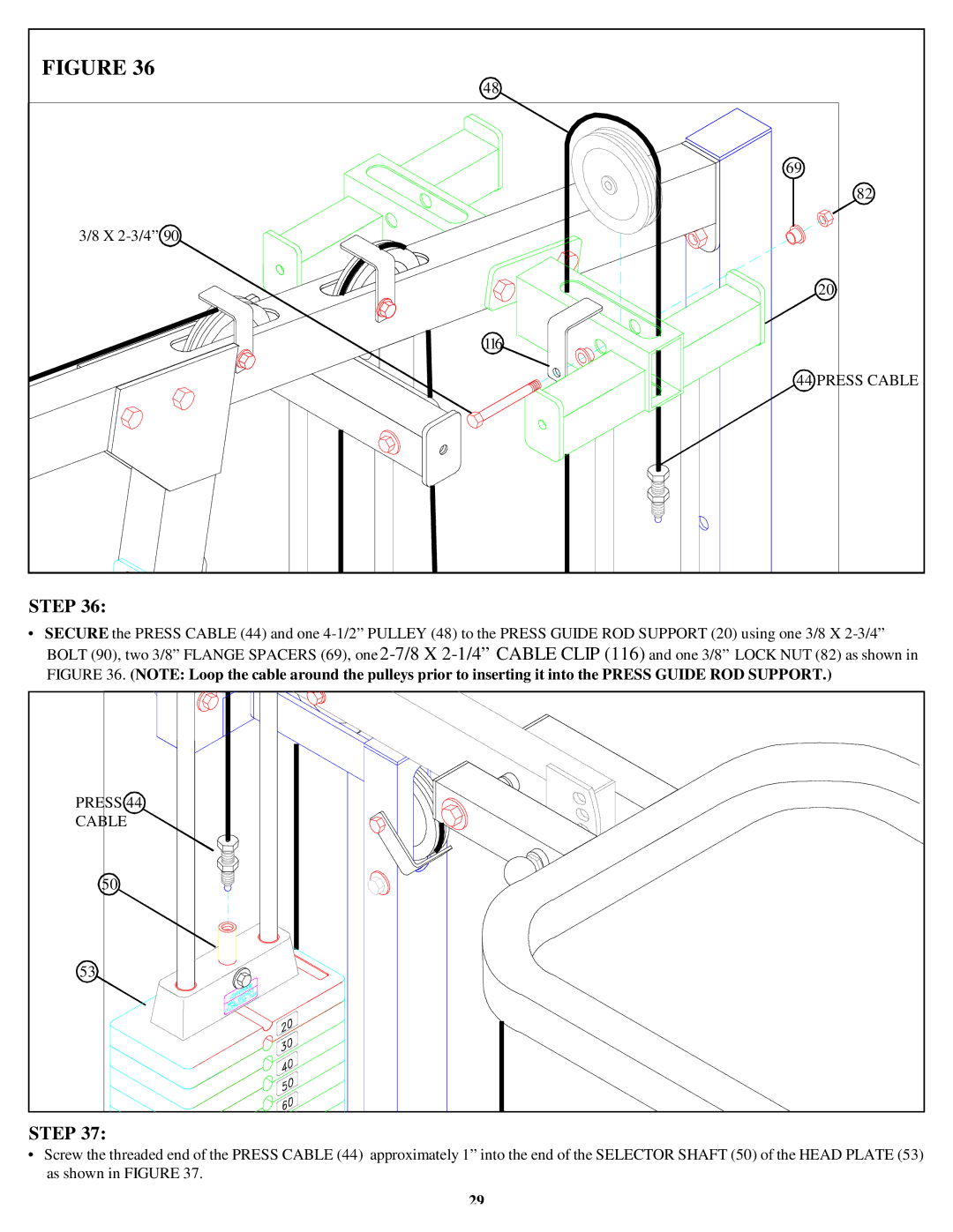
STEP 36:
•SECURE the PRESS CABLE (44) and one
PRESS 44 |
CABLE |
50 |
53 |
STEP 37:
•Screw the threaded end of the PRESS CABLE (44) approximately 1” into the end of the SELECTOR SHAFT (50) of the HEAD PLATE (53) as shown in FIGURE 37.
29