42 LAT CABLE
50
53
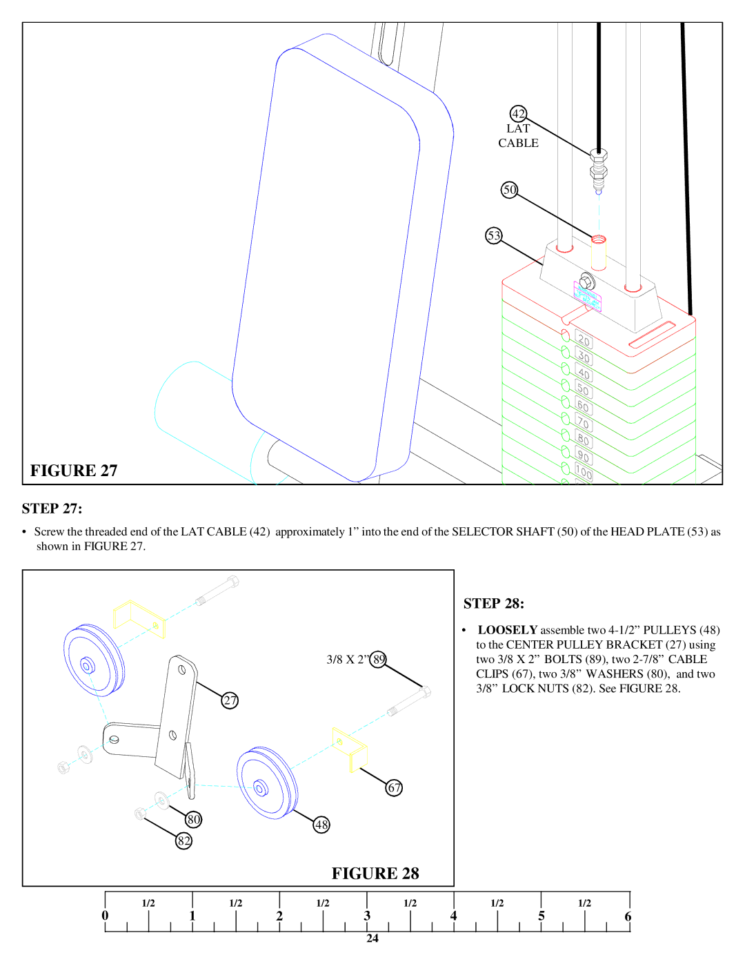
FIGURE 27
STEP 27:
•Screw the threaded end of the LAT CABLE (42) approximately 1” into the end of the SELECTOR SHAFT (50) of the HEAD PLATE (53) as shown in FIGURE 27.
80
82
STEP 28: | |
• | LOOSELY assemble two |
| to the CENTER PULLEY BRACKET (27) using |
3/8 X 2” 89 | two 3/8 X 2” BOLTS (89), two |
| CLIPS (67), two 3/8” WASHERS (80), and two |
| 3/8” LOCK NUTS (82). See FIGURE 28. |
27
67
48
FIGURE 28
1/2
1/2
1/2
1/2
1/2
1/2
0
1
2
3
4
5
6
24