Power-Up Sequence
•The USB Wizard can be powered at any time.
•The CPUs can be powered at any time although if a CPU needs a keyboard and/or mouse at
•USB input devices (keyboard and mouse) can be hot plugged to and from the USB Wizard switch at any time.
If the security option is enabled (see page 12 for details on the "Security Option"), when the USB Wizard is powered up the user will be prompted for a username and password to continue. If the security option is not enabled the monitor will display the desktop image for the connected CPU and the user can continue with normal operation of the connected CPU.
Limitations
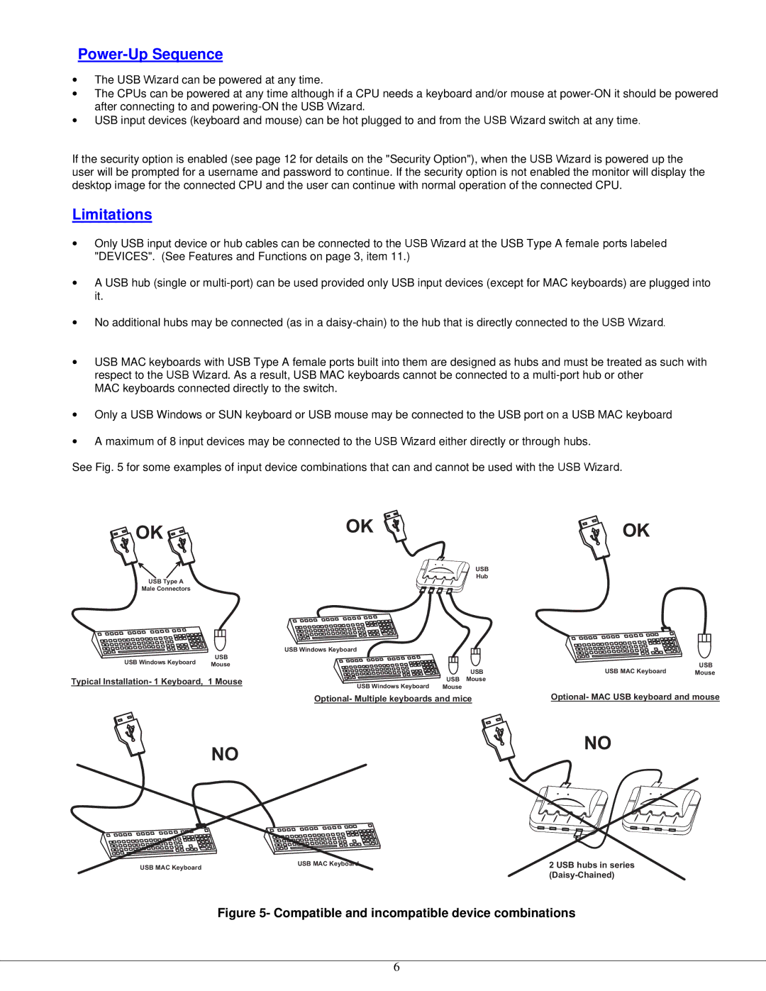
•Only USB input device or hub cables can be connected to the USB Wizard at the USB Type A female ports labeled "DEVICES". (See Features and Functions on page 3, item 11.)
•A USB hub (single or
•No additional hubs may be connected (as in a
•USB MAC keyboards with USB Type A female ports built into them are designed as hubs and must be treated as such with respect to the USB Wizard. As a result, USB MAC keyboards cannot be connected to a
MAC keyboards connected directly to the switch.
•Only a USB Windows or SUN keyboard or USB mouse may be connected to the USB port on a USB MAC keyboard
•A maximum of 8 input devices may be connected to the USB Wizard either directly or through hubs.
See Fig. 5 for some examples of input device combinations that can and cannot be used with the USB Wizard.
O K | O K | O K |
| ||
|
| U S B |
|
| H u b |
U S B | T y p e A |
|
M a l e C o n n e c t o r s
U S B W i n d o w s K e y b o a r d |
| |
U S B |
|
|
U S B W i n d o w s K e y b o a r d |
| U S B |
M o u s e |
| |
| U S B | U S B M A C K e y b o a r d |
| M o u s e | |
T y p i c a l I n s t a l l a t i o n - 1 | U SM Bo u s e |
|
K e y b o a r d , 1 M o u s e |
| |
| U S B W i n d oMwosu sK ee y b o a r d |
|
O p t i o n a l - M A C U S B
O p t i o n a l - M u l t i p l e k e y b o a r d s a n d m i c
N O
N O
U S B M A C K e y b o a r d | 2 U S B h u b s i n s e r |
U S B M A C K e y b o a r d |
|
| ( D a i s y - C h a i n e d ) |
Figure 5- Compatible and incompatible device combinations
6
