INSTALLATION | ||
|
|
|
OUTPUT CONNECTIONS
![]() WARNING
WARNING
ELECTRIC SHOCK can kill.
•Keep the electrode holder, TIG torch and cable insulation in good condition and in place.
•Do not touch electrically live parts or electrode with skin or wet cloth- ing.
•Insulate yourself from work and ground.
•Turn the input line Switch on the Invertec
OUTPUT AND GAS CONNECTION FOR TIG WELDING (FIGURE A.1)
The TIG Torch
WARNING
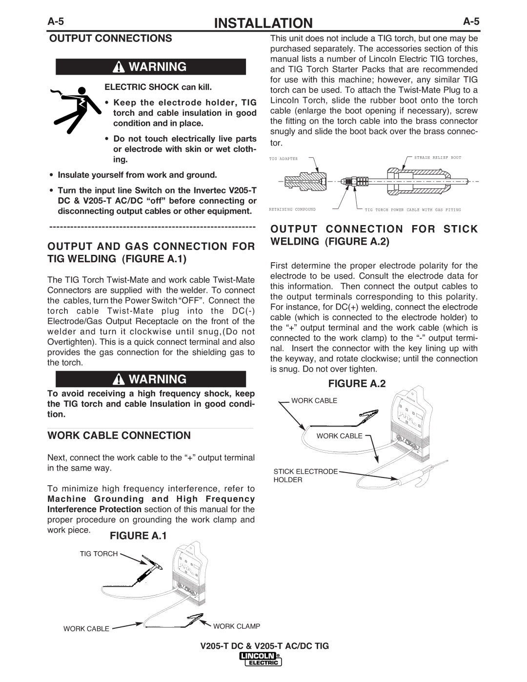
This unit does not include a TIG torch, but one may be purchased separately. The accessories section of this manual lists a number of Lincoln Electric TIG torches, and TIG Torch Starter Packs that are recommended for use with this machine; however, any similar TIG torch can be used. To attach the
TIG ADAPTER |
|
|
|
|
|
|
|
|
|
|
|
|
|
|
|
|
|
|
|
|
|
|
|
|
|
|
|
|
|
|
|
|
|
|
|
| STRAIN RELIEF BOOT | ||||||||||||||
|
|
|
|
|
|
|
|
|
|
|
|
|
|
|
|
|
|
|
|
|
|
|
|
|
|
|
|
|
|
| |||||||||||||||||||||
|
|
|
|
|
|
|
|
|
|
|
|
|
|
|
|
|
|
|
|
|
|
|
|
|
|
|
|
|
|
|
|
|
|
|
|
|
|
|
|
|
|
|
|
|
|
|
|
|
|
|
|
|
|
|
|
|
|
|
|
|
|
|
|
|
|
|
|
|
|
|
|
|
|
|
|
|
|
|
|
|
|
|
|
|
|
|
|
|
|
|
|
|
|
|
|
|
|
|
|
|
|
|
|
|
|
|
|
|
|
|
|
|
|
|
|
|
|
|
|
|
|
|
|
|
|
|
|
|
|
|
|
|
|
|
|
|
|
|
|
|
|
|
|
|
|
|
|
|
|
|
|
|
|
|
|
RETAINING COMPOUND | TIG TORCH POWER CABLE WITH GAS FITING |
OUTPUT CONNECTION FOR STICK WELDING (FIGURE A.2)
First determine the proper electrode polarity for the electrode to be used. Consult the electrode data for this information. Then connect the output cables to the output terminals corresponding to this polarity. For instance, for DC(+) welding, connect the electrode cable (which is connected to the electrode holder) to the “+” output terminal and the work cable (which is connected to the work clamp) to the
To avoid receiving a high frequency shock, keep the TIG torch and cable Insulation in good condi- tion.
___________________________________________
WORK CABLE CONNECTION
Next, connect the work cable to the “+” output terminal in the same way.
To minimize high frequency interference, refer to
Machine Grounding and High Frequency Interference Protection section of this manual for the proper procedure on grounding the work clamp and work piece.
TIG TORCH ![]()
- ![]()
![]()
![]()
![]() +
+
FIGURE A.2
WORK CABLE
WORK CABLE
STICK ELECTRODE
HOLDER
-![]()
![]()
![]()
![]()
![]()
![]()
![]()
![]() +
+
WORK CABLE | WORK CLAMP |
|