Output Connections
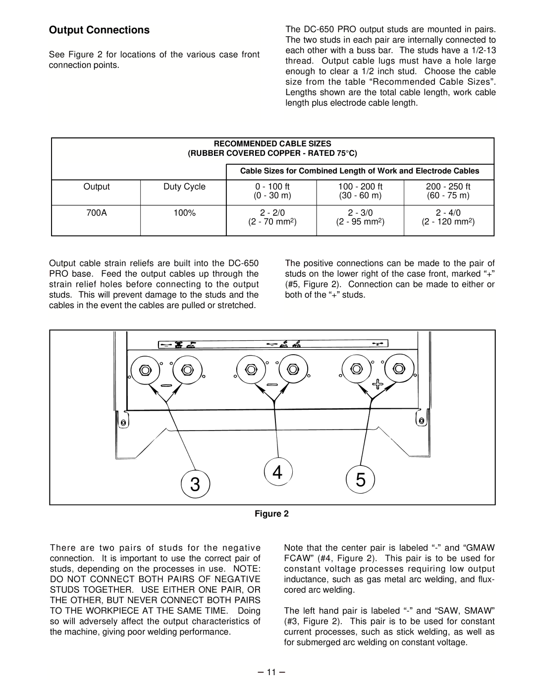
See Figure 2 for locations of the various case front connection points.
The
RECOMMENDED CABLE SIZES
(RUBBER COVERED COPPER - RATED 75°C)
|
|
|
|
|
|
|
|
|
|
|
| Cable Sizes for Combined Length of Work and Electrode Cables |
| ||||
|
|
|
|
|
|
|
|
|
Output | Duty Cycle |
| 0 - 100 ft | 100 | - 200 ft | 200 | - 250 ft | |
|
|
| (0 - 30 m) | (30 - 60 m) | (60 - 75 m) | |||
|
|
|
|
|
|
|
|
|
700A | 100% |
| 2 - 2/0 | 2 | - 3/0 | 2 | - 4/0 |
|
|
|
| (2 - 70 mm2) | (2 - 95 mm2) | (2 - 120 mm2) | |||
|
|
|
|
|
|
|
|
|
Output cable strain reliefs are built into the
The positive connections can be made to the pair of studs on the lower right of the case front, marked “+” (#5, Figure 2). Connection can be made to either or both of the “+” studs.
3 4 5
Figure 2
There are two pairs of studs for the negative connection. It is important to use the correct pair of studs, depending on the processes in use. NOTE:
DO NOT CONNECT BOTH PAIRS OF NEGATIVE STUDS TOGETHER. USE EITHER ONE PAIR, OR THE OTHER, BUT NEVER CONNECT BOTH PAIRS TO THE WORKPIECE AT THE SAME TIME. Doing so will adversely affect the output characteristics of the machine, giving poor welding performance.
Note that the center pair is labeled
The left hand pair is labeled
– 11 –