Wire Feeder Control Cable Connections
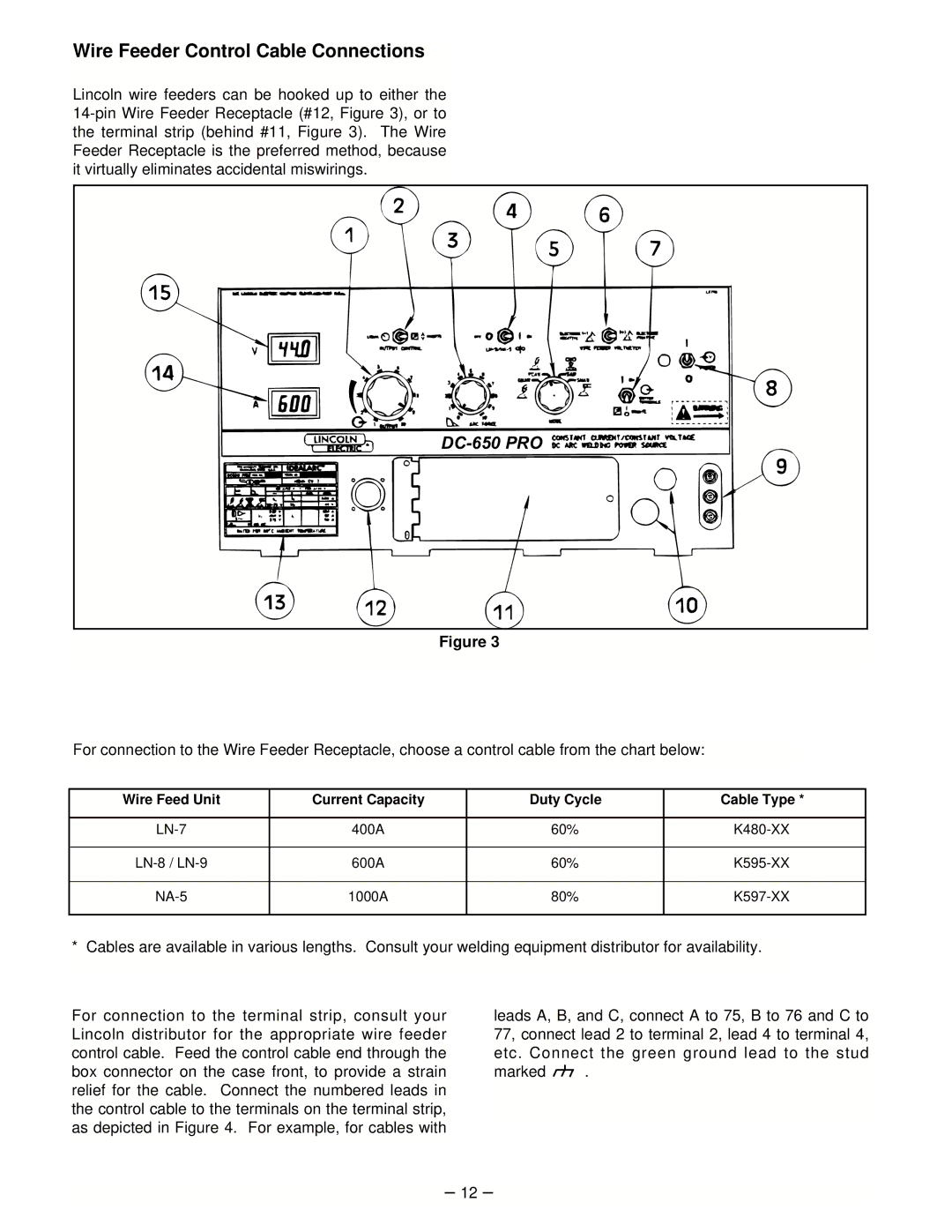
Lincoln wire feeders can be hooked up to either the
|
Figure 3
For connection to the Wire Feeder Receptacle, choose a control cable from the chart below:
Wire Feed Unit | Current Capacity | Duty Cycle | Cable Type * |
|
|
|
|
400A | 60% | ||
|
|
|
|
600A | 60% | ||
|
|
|
|
1000A | 80% | ||
|
|
|
|
* Cables are available in various lengths. Consult your welding equipment distributor for availability.
For connection to the terminal strip, consult your Lincoln distributor for the appropriate wire feeder control cable. Feed the control cable end through the box connector on the case front, to provide a strain relief for the cable. Connect the numbered leads in the control cable to the terminals on the terminal strip, as depicted in Figure 4. For example, for cables with
leads A, B, and C, connect A to 75, B to 76 and C to 77, connect lead 2 to terminal 2, lead 4 to terminal 4, etc. Connect the green ground lead to the stud
marked ![]()
![]()
![]() .
.
– 12 –