Connection of a K775 Remote Output Control
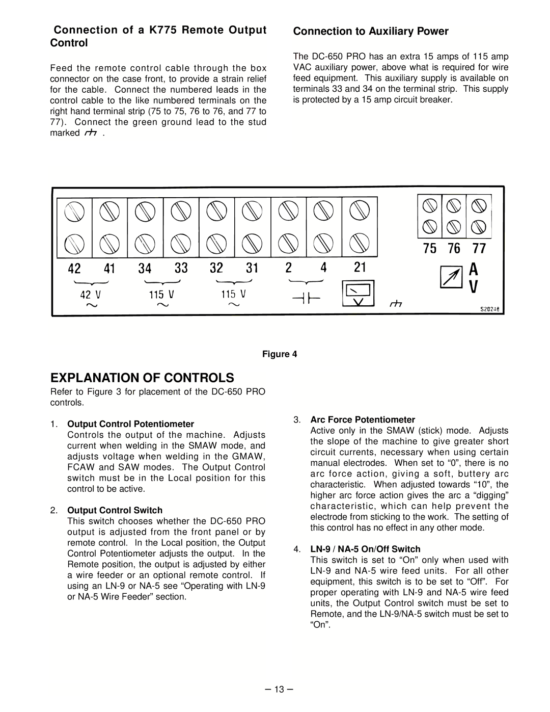
Feed the remote control cable through the box connector on the case front, to provide a strain relief for the cable. Connect the numbered leads in the control cable to the like numbered terminals on the right hand terminal strip (75 to 75, 76 to 76, and 77 to
77). Connect the green ground lead to the stud
marked ![]()
![]()
![]() .
.
Connection to Auxiliary Power
The
Figure 4
EXPLANATION OF CONTROLS
Refer to Figure 3 for placement of the
1.Output Control Potentiometer
Controls the output of the machine. Adjusts current when welding in the SMAW mode, and adjusts voltage when welding in the GMAW, FCAW and SAW modes. The Output Control switch must be in the Local position for this control to be active.
2.Output Control Switch
This switch chooses whether the
3.Arc Force Potentiometer
Active only in the SMAW (stick) mode. Adjusts the slope of the machine to give greater short circuit currents, necessary when using certain manual electrodes. When set to “0”, there is no arc force action, giving a soft, buttery arc characteristic. When adjusted towards “10”, the higher arc force action gives the arc a “digging” characteristic, which can help prevent the electrode from sticking to the work. The setting of this control has no effect in any other mode.
4.LN-9 / NA-5 On/Off Switch
This switch is set to “On” only when used with
– 13 –