INSTALLATION | ||
|
|
|
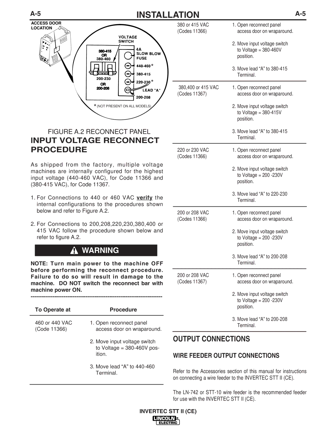
ACCESS DOOR
LOCATION
4A | |
| |
OR |
|
| * |
OR ![]() *
*
*(NOT PRESENT ON ALL MODELS)
FIGURE A.2 RECONNECT PANEL
INPUT VOLTAGE RECONNECT PROCEDURE
As shipped from the factory, multiple voltage machines are internally configured for the highest input voltage
1.For Connections to 440 or 460 VAC verify the internal configurations to the procedures shown below and refer to Figure A.2.
2.For Connections to 200,208,220,230,380,400 or 415 VAC follow the procedure shown below and refer to figure A.2.
![]() WARNING
WARNING
NOTE: Turn main power to the machine OFF before performing the reconnect procedure. Failure to do so will result in damage to the machine. DO NOT switch the reconnect bar with machine power ON.
To Operate at |
| Procedure |
|
| |
460 or 440 VAC | 1. Open reconnect panel | |
(Code 11366) |
| access door on wraparound. |
| 2. | Move input voltage switch |
|
| to Voltage = |
|
| ition. |
| 3. | Move lead “A” to |
|
| Terminal. |
|
|
|
380 or 415 VAC | 1. Open reconnect panel | |
(Codes 11366) |
| access door on wraparound. |
| 2. | Move input voltage switch |
|
| to Voltage = |
|
| position. |
| 3. | Move lead “A” to |
|
| Terminal. |
|
| |
380,400 or 415 VAC | 1. Open reconnect panel | |
(Codes 11367) |
| access door on wraparound. |
| 2. | Move input voltage switch |
|
| to Voltage = |
|
| position. |
| 3. | Move lead “A” to |
|
| Terminal. |
|
| |
220 or 230 VAC | 1. Open reconnect panel | |
(Codes 11366) |
| access door on wraparound. |
| 2. | Move input voltage switch |
|
| to Voltage = 200 |
|
| position. |
| 3. | Move lead “A” to |
|
| Terminal. |
|
| |
200 or 208 VAC | 1. Open reconnect panel | |
(Codes 11366) |
| access door on wraparound. |
| 2. | Move input voltage switch |
|
| to Voltage = 200 |
|
| position. |
| 3. | Move lead “A” to |
|
| Terminal. |
|
| |
200 or 208 VAC | 1. Open reconnect panel | |
(Codes 11367) |
| access door on wraparound. |
| 2. | Move input voltage switch |
|
| to Voltage = 200 |
|
| position. |
| 3. | Move lead “A” to |
|
| Terminal. |
|
|
|
OUTPUT CONNECTIONS
WIRE FEEDER OUTPUT CONNECTIONS
Refer to the Accessories section of this manual for instructions on connecting a wire feeder to the INVERTEC STT II (CE).
The
INVERTEC STT II (CE)