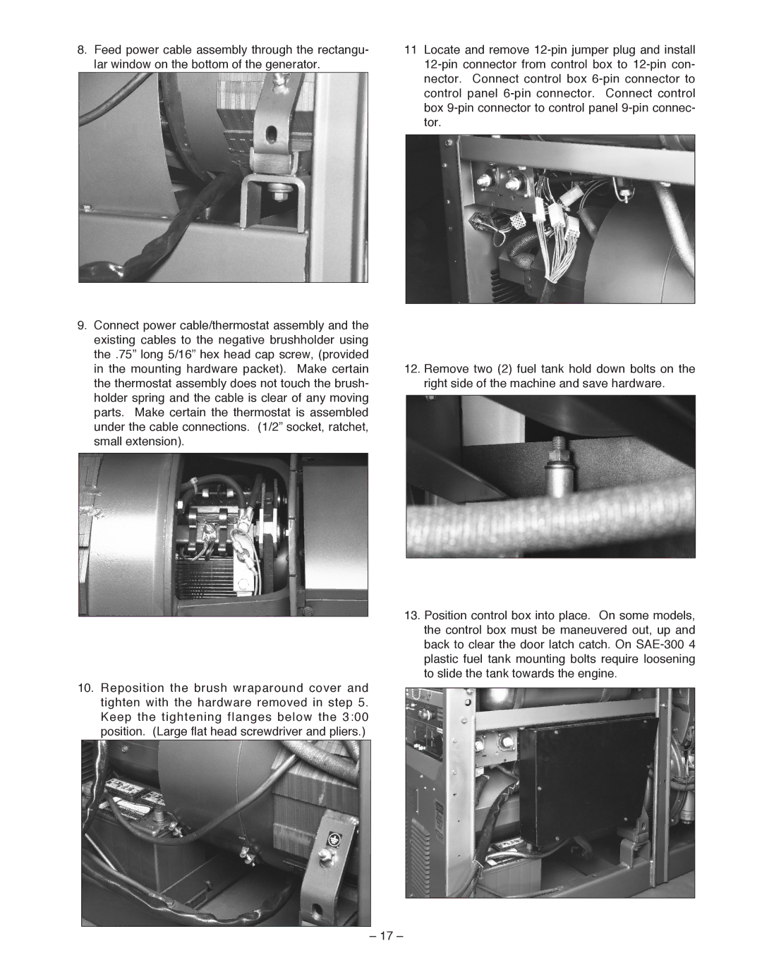
8.Feed power cable assembly through the rectangu- lar window on the bottom of the generator.
9.Connect power cable/thermostat assembly and the existing cables to the negative brushholder using the .75” long 5/16” hex head cap screw, (provided in the mounting hardware packet). Make certain the thermostat assembly does not touch the brush- holder spring and the cable is clear of any moving parts. Make certain the thermostat is assembled under the cable connections. (1/2” socket, ratchet, small extension).
10.Reposition the brush wraparound cover and tighten with the hardware removed in step 5. Keep the tightening flanges below the 3:00 position. (Large flat head screwdriver and pliers.)
11Locate and remove
12.Remove two (2) fuel tank hold down bolts on the right side of the machine and save hardware.
13.Position control box into place. On some models, the control box must be maneuvered out, up and back to clear the door latch catch. On
– 17 –