18)Position control box into place. On some models, the control box must be maneuvered out, up and back to clear the door latch catch. On Classic II machines, make sure the battery cable is not caught between the wire feed module and generator.
19)Install flat washer, lockwasher, and hex nut to control box mounting studs and tighten. (9/16” Socket, ratchet, and 9/16” open end wrench).
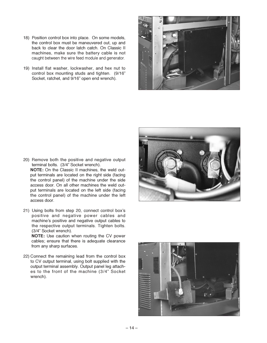
20)Remove both the positive and negative output terminal bolts. (3/4” Socket wrench).
NOTE: On the Classic II machines, the weld out- put terminals are located on the right side (facing the control panel) of the machine under the side access door. On all other machines the weld out- put terminals are located on the left side (facing the control panel) of the machine under the left access door.
21)Using bolts from step 20, connect control box’s positive and negative power cables and machine’s positive and negative output cables to the respective output terminals. Tighten bolts. (3/4” Socket wrench).
NOTE: Use caution when routing the CV power cables; ensure that there is adequate clearance from any sharp surfaces.
22)Connect the remaining lead from the control box to CV output terminal, using bolt supplied with the output terminal assembly. Output panel leg attach- es to the front of the machine (3/4” Socket wrench).
– 14 –