ASSEMBLY INTO SAE-300 WELDER: INSTALLATION SEQUENCE:
(For Code 11806 )
1.Remove the bottom 3 mounting screws from the upper control nameplate. Keep the screws for later use to fasten the WFM nameplate. Once, the screws have been removed snap / break off the lower section of the nameplate (the section with the welder name on it).
![]() 1. Remove 3 mounting screws.
1. Remove 3 mounting screws.
2.Snap or Break off lower section on this dotted line.
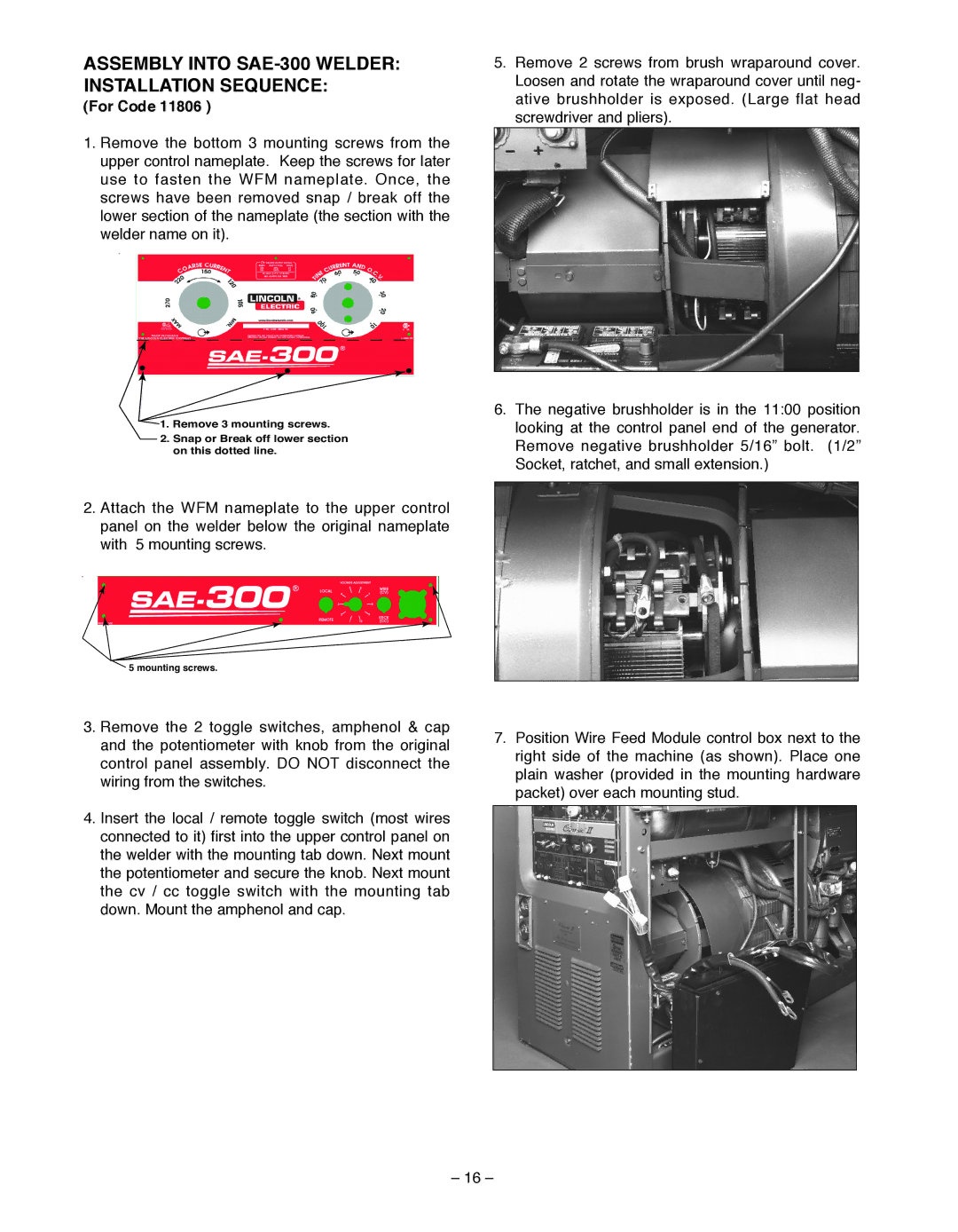
2.Attach the WFM nameplate to the upper control panel on the welder below the original nameplate with 5 mounting screws.
![]() 5 mounting screws.
5 mounting screws.
5.Remove 2 screws from brush wraparound cover. Loosen and rotate the wraparound cover until neg- ative brushholder is exposed. (Large flat head screwdriver and pliers).
6.The negative brushholder is in the 11:00 position looking at the control panel end of the generator. Remove negative brushholder 5/16” bolt. (1/2” Socket, ratchet, and small extension.)
3.Remove the 2 toggle switches, amphenol & cap and the potentiometer with knob from the original control panel assembly. DO NOT disconnect the wiring from the switches.
4.Insert the local / remote toggle switch (most wires connected to it) first into the upper control panel on the welder with the mounting tab down. Next mount the potentiometer and secure the knob. Next mount the cv / cc toggle switch with the mounting tab down. Mount the amphenol and cap.
7.Position Wire Feed Module control box next to the right side of the machine (as shown). Place one plain washer (provided in the mounting hardware packet) over each mounting stud.
– 16 –