14.Mount the WFM using .62 spacers, flat washer, lock washer and hex nuts provided in the mount- ing hardware packet. Tighten all fuel tank bolts to rail.
15.Remove both the positive and negative output ter- minal bolts. (3/4” Socket wrench).
16.Using bolts from step 15, connect control box’s positive and negative power cables and machine’s positive and negative output cables to the respective output terminals. Tighten bolts. (3/4” Socket wrench).
NOTE: Use caution when routing the CV power cables; ensure that there is adequate clearance from any sharp surfaces.
17.Connect the remaining lead from the control box to CV output terminal, using bolt supplied with the output terminal assembly. Output panel leg attach- es to the front of the machine (3/4” Socket wrench).
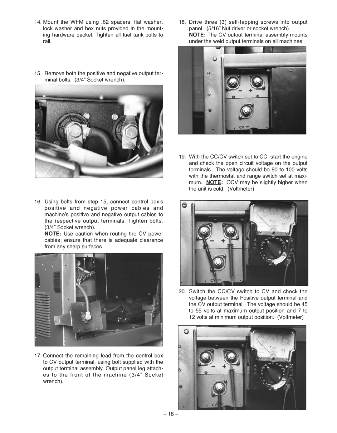
18.Drive three (3)
19.With the CC/CV switch set to CC, start the engine and check the open circuit voltage on the output terminals. The voltage should be 80 to 100 volts with the thermostat and range switch set at maxi- mum. NOTE: OCV may be slightly higher when the unit is cold. (Voltmeter)
20.Switch the CC/CV switch to CV and check the voltage between the Positive output terminal and the CV output terminal. The voltage should be 45 to 55 volts at maximum output position and 7 to 12 volts at minimum output position. (Voltmeter)
– 18 –
