OPERATION | ||
|
|
|
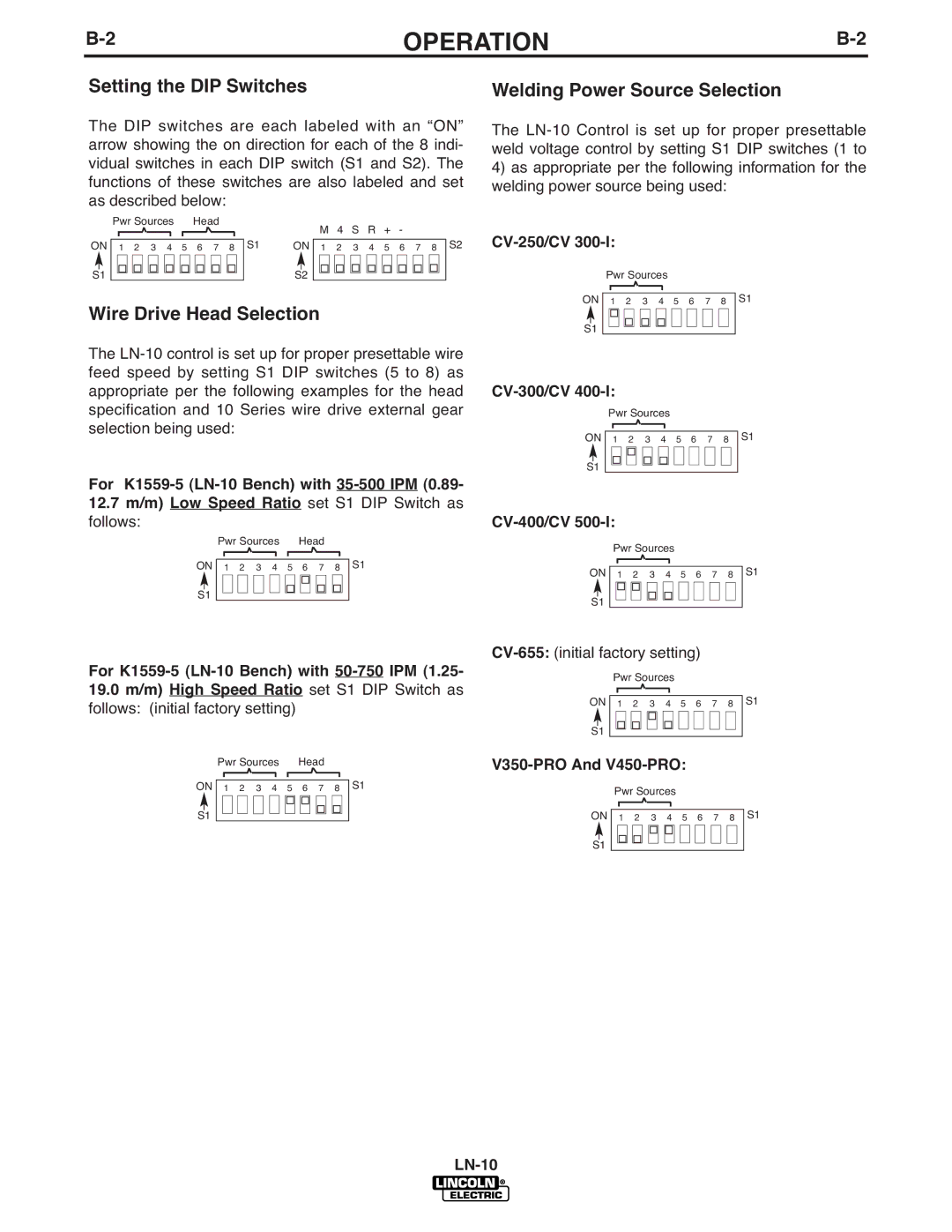
Setting the DIP Switches
The DIP switches are each labeled with an “ON” arrow showing the on direction for each of the 8 indi- vidual switches in each DIP switch (S1 and S2). The functions of these switches are also labeled and set as described below:
| Pwr Sources Head |
|
| M 4 S R | + - |
|
| ||||||||||||||
ON |
|
|
|
|
|
|
|
|
|
|
|
|
|
| S1 | ON |
|
| S2 | ||
|
|
|
|
|
|
|
|
|
|
|
|
|
|
|
|
|
| ||||
|
|
|
|
|
|
|
|
|
|
|
|
|
|
|
|
|
| ||||
1 2 3 4 5 6 7 8 |
|
| 1 2 3 4 | 5 6 7 8 | |||||||||||||||||
S1 | S2 |
Wire Drive Head Selection
The
For
12.7m/m) Low Speed Ratio set S1 DIP Switch as follows:
|
|
| Pwr Sources |
|
| Head |
|
|
|
| |||||||||||||
ON |
|
|
|
|
|
|
|
|
|
|
|
|
|
|
|
|
|
|
|
| S1 | ||
|
|
|
|
|
|
|
|
|
|
|
|
|
|
|
|
|
|
|
| ||||
| 1 | 2 | 3 | 4 | 5 | 6 |
|
| 7 |
| 8 |
|
| ||||||||||
|
|
|
|
|
|
|
|
|
|
|
|
|
|
|
|
|
|
|
|
|
|
|
|
S1 |
|
|
|
|
|
|
|
|
|
|
|
|
|
|
|
|
|
|
|
|
| ||
|
|
|
|
|
|
|
|
|
|
|
|
|
|
|
|
|
|
|
|
| |||
For K1559-5 (LN-10 Bench) with 50-750 IPM (1.25-
19.0m/m) High Speed Ratio set S1 DIP Switch as follows: (initial factory setting)
|
|
| Pwr Sources |
|
|
| Head |
|
|
|
|
| ||||||||||||||
ON |
|
|
|
|
|
|
|
|
|
|
|
|
|
|
|
|
|
|
|
|
|
|
| S1 | ||
| 1 | 2 | 3 | 4 | 5 | 6 |
|
| 7 |
| 8 |
|
| |||||||||||||
|
|
|
|
|
|
|
|
|
|
|
|
|
|
|
|
|
|
|
|
|
|
|
|
|
|
|
S1 |
|
|
|
|
|
|
|
|
|
|
|
|
|
|
|
|
|
|
|
|
|
|
|
| ||
|
|
|
|
|
|
|
|
|
|
|
|
|
|
|
|
|
|
|
|
|
|
|
| |||
Welding Power Source Selection
The
4)as appropriate per the following information for the welding power source being used:
Pwr Sources
ON |
|
|
|
|
|
|
|
|
| S1 |
1 | 2 | 3 | 4 | 5 | 6 | 7 | 8 | |||
|
|
|
|
|
|
|
|
|
|
|
|
|
|
|
|
|
|
|
|
|
|
S1
Pwr Sources
ON |
|
|
|
|
|
|
|
| S1 |
1 | 2 | 3 | 4 | 5 | 6 | 7 | 8 | ||
|
|
|
|
|
|
|
|
|
|
|
|
|
|
|
|
|
|
|
|
S1
Pwr Sources
ON |
|
|
|
|
|
|
|
|
|
| S1 |
1 | 2 | 3 | 4 | 5 | 6 | 7 | 8 | ||||
|
|
|
|
|
|
|
|
|
|
|
|
|
|
|
|
|
|
|
|
|
|
|
|
S1
Pwr Sources
ON |
|
|
|
|
|
|
|
| S1 |
1 | 2 | 3 | 4 | 5 | 6 | 7 | 8 | ||
|
|
|
|
|
|
|
|
|
|
|
|
|
|
|
|
|
|
|
|
S1
Pwr Sources
ON |
|
|
|
|
|
|
|
|
| S1 | |
1 | 2 | 3 | 4 | 5 | 6 | 7 | 8 | ||||
|
|
|
|
|
|
|
|
|
|
|
|
|
|
|
|
|
|
|
|
|
|
|
|
|
|
|
|
|
|
|
|
|
|
|
|
|
|
|
|
|
|
|
|
|
|
|
|
S1