OPERATION | ||
|
|
|
Pwr Sources
ON |
|
|
|
|
|
|
|
|
| S1 |
1 | 2 | 3 | 4 | 5 | 6 | 7 | 8 | |||
|
|
|
|
|
|
|
|
|
|
|
|
|
|
|
|
|
|
|
|
|
|
|
|
|
|
|
|
|
|
|
|
|
S1
Pwr Sources
ON |
|
|
|
|
|
|
|
|
| S1 |
1 | 2 | 3 | 4 | 5 | 6 | 7 | 8 | |||
|
|
|
|
|
|
|
|
|
|
|
|
|
|
|
|
|
|
|
|
|
|
S1
Pwr Sources
ON |
|
|
|
|
|
|
|
|
|
|
| S1 |
1 | 2 | 3 | 4 | 5 | 6 | 7 | 8 | |||||
|
|
|
|
|
|
|
|
|
|
|
|
|
|
|
|
|
|
|
|
|
|
|
|
|
|
S1
Pwr Sources
ON |
|
|
|
|
|
|
|
| S1 |
1 | 2 | 3 | 4 | 5 | 6 | 7 | 8 | ||
|
|
|
|
|
|
|
|
|
|
|
|
|
|
|
|
|
|
|
|
S1
Pwr Sources
ON |
|
|
|
|
|
|
|
|
| S1 | |
1 | 2 | 3 | 4 | 5 | 6 | 7 | 8 | ||||
|
|
|
|
|
|
|
|
|
|
|
|
|
|
|
|
|
|
|
|
|
|
|
|
|
|
|
|
|
|
|
|
|
|
|
|
S1
Pulse Power 500: *
Pwr Sources
ON |
|
|
|
|
|
|
|
| S1 |
1 | 2 | 3 | 4 | 5 | 6 | 7 | 8 | ||
|
|
|
|
|
|
|
|
|
|
|
|
|
|
|
|
|
|
|
|
S1
V300 PRO:
Pwr Sources
ON |
|
|
|
|
|
|
|
|
|
| S1 |
1 |
| 2 | 3 | 4 | 5 | 6 | 7 | 8 | |||
|
|
|
|
|
|
|
|
|
|
|
|
|
|
|
|
|
|
|
|
|
|
|
|
|
|
|
|
|
|
|
|
|
|
|
|
S1
10.0 TO 45.0 VOLT LINEAR PRESET
(FOR POWER SOURCES WITH LINEAR VOLTAGE CONTROL PROTOCOL)
Pwr Sources
ON |
|
|
|
|
|
|
|
|
|
| S1 |
1 | 2 | 3 |
| 4 | 5 | 6 | 7 | 8 | |||
|
|
|
|
|
|
|
|
|
|
|
|
|
|
|
|
|
|
|
|
|
|
|
|
S1
0.0 TO 10.0 LINEAR PRESET:
Pwr Sources
ON |
|
|
|
|
|
|
|
| S1 |
1 | 2 | 3 | 4 | 5 | 6 | 7 | 8 |
S1
*Requires optional
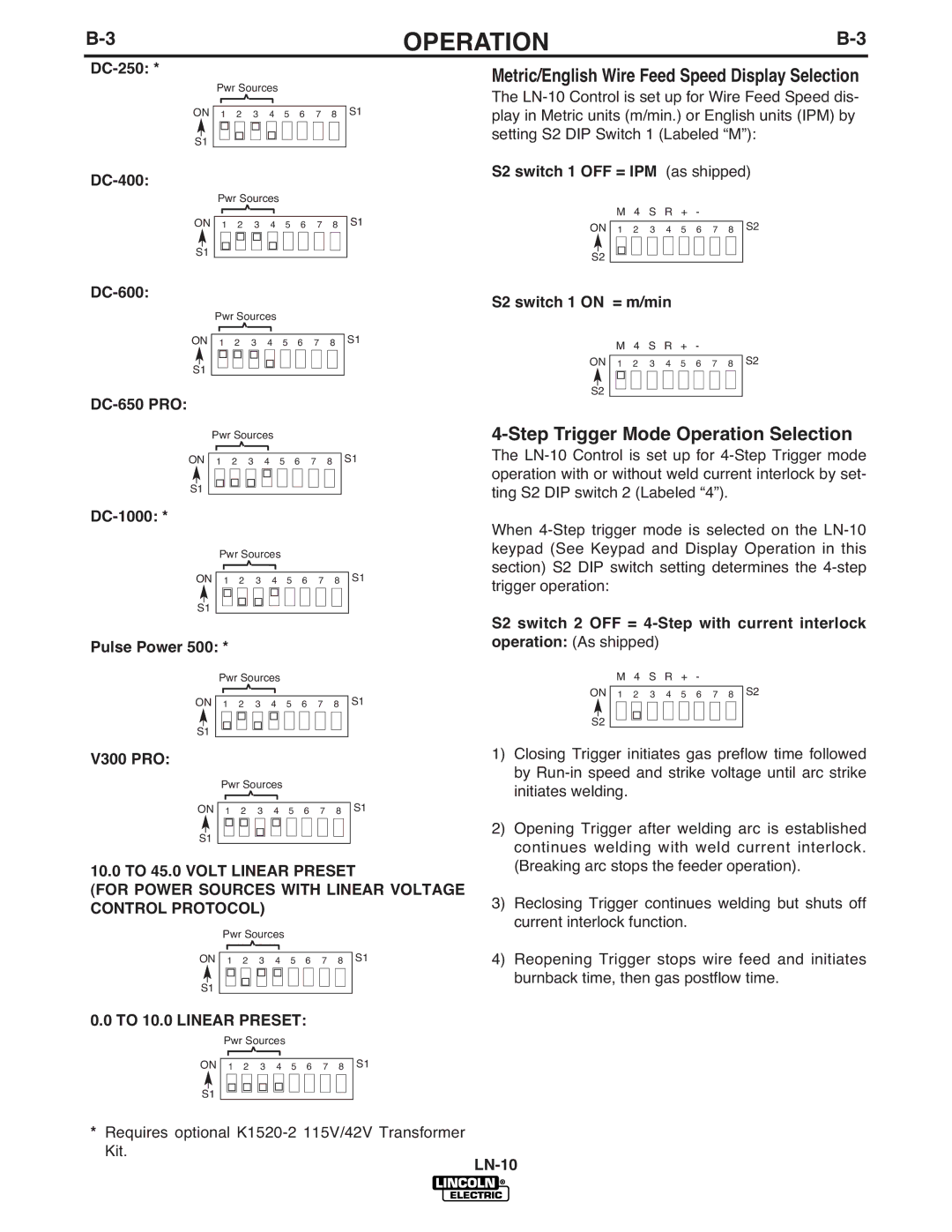
Metric/English Wire Feed Speed Display Selection
The
S2 switch 1 OFF = IPM (as shipped)
|
|
| M | 4 | S | R | + | - |
|
|
|
|
ON |
| 1 | 2 | 3 | 4 | 5 | 6 | 7 | 8 |
| S2 | |
|
|
|
|
|
|
|
|
|
|
|
|
|
|
|
|
|
|
|
|
|
|
|
|
| |
|
|
|
|
|
|
|
|
|
|
|
|
|
S2 |
|
|
|
|
|
|
|
|
|
|
| |
S2 switch 1 ON = m/min
|
|
| M | 4 | S | R | + | - |
|
|
|
| ||
ON |
| 1 |
| 2 | 3 | 4 | 5 | 6 | 7 | 8 |
| S2 | ||
|
|
|
|
|
|
|
|
|
|
|
|
|
|
|
|
|
|
|
|
|
|
|
|
|
|
|
|
|
|
|
|
|
|
|
|
|
|
|
|
|
|
|
|
|
S2 |
|
|
|
|
|
|
|
|
|
|
|
|
| |
4-Step Trigger Mode Operation Selection
The
When
S2 switch 2 OFF =
|
|
|
| M | 4 | S | R | + | - |
|
|
|
| |
ON |
|
|
|
|
|
|
|
|
|
|
| S2 | ||
| 1 | 2 | 3 | 4 | 5 | 6 | 7 | 8 |
| |||||
|
|
|
|
|
|
|
|
|
|
|
|
|
|
|
S2 |
|
|
|
|
|
|
|
|
|
|
|
| ||
|
|
|
|
|
|
|
|
|
|
|
| |||
1)Closing Trigger initiates gas preflow time followed by
2)Opening Trigger after welding arc is established continues welding with weld current interlock. (Breaking arc stops the feeder operation).
3)Reclosing Trigger continues welding but shuts off current interlock function.
4)Reopening Trigger stops wire feed and initiates burnback time, then gas postflow time.