OPERATION | ||
|
|
|
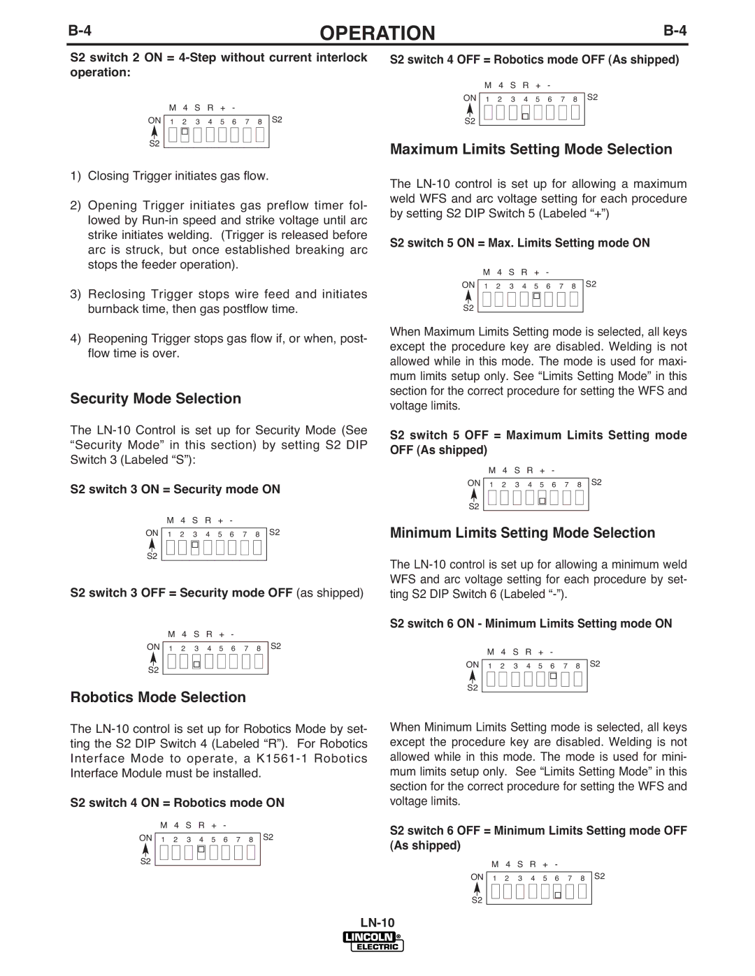
S2 switch 2 ON = 4-Step without current interlock operation:
|
|
| M | 4 | S | R | + | - |
|
|
|
|
ON |
| 1 | 2 | 3 | 4 | 5 | 6 | 7 | 8 |
| S2 | |
|
|
|
|
|
|
|
|
|
|
|
|
|
|
|
|
|
|
|
|
|
|
|
|
| |
|
|
|
|
|
|
|
|
|
|
|
|
|
S2 |
|
|
|
|
|
|
|
|
|
|
| |
1)Closing Trigger initiates gas flow.
2)Opening Trigger initiates gas preflow timer fol- lowed by
3)Reclosing Trigger stops wire feed and initiates burnback time, then gas postflow time.
4)Reopening Trigger stops gas flow if, or when, post- flow time is over.
Security Mode Selection
The
S2 switch 3 ON = Security mode ON
|
|
|
| M | 4 | S | R | + | - |
|
|
|
| ||
ON |
|
|
|
|
|
|
|
|
|
|
|
| S2 | ||
| 1 | 2 | 3 |
| 4 | 5 | 6 | 7 | 8 |
| |||||
|
|
|
|
|
|
|
|
|
|
|
|
|
|
|
|
|
|
|
|
|
|
|
|
|
|
|
|
|
|
|
|
S2 |
|
|
|
|
|
|
|
|
|
|
|
|
| ||
S2 switch 3 OFF = Security mode OFF (as shipped)
|
|
| M | 4 | S | R | + | - |
|
|
|
| ||
ON |
|
|
|
|
|
|
|
|
|
|
|
| S2 | |
| 1 | 2 | 3 |
| 4 | 5 | 6 | 7 | 8 |
| ||||
|
|
|
|
|
|
|
|
|
|
|
|
|
|
|
|
|
|
|
|
|
|
|
|
|
|
|
|
|
|
S2 |
|
|
|
|
|
|
|
|
|
|
|
|
| |
|
|
|
|
|
|
|
|
|
|
|
|
| ||
Robotics Mode Selection
The
S2 switch 4 ON = Robotics mode ON
|
|
| M | 4 | S | R | + | - |
|
|
|
|
ON |
|
|
|
|
|
|
|
|
|
| S2 | |
| 1 | 2 | 3 | 4 | 5 | 6 | 7 | 8 |
| |||
|
|
|
|
|
|
|
|
|
|
|
| |
|
|
|
|
|
|
|
|
|
|
|
|
|
S2 |
|
|
|
|
|
|
|
|
|
|
| |
S2 switch 4 OFF = Robotics mode OFF (As shipped)
|
|
| M | 4 | S | R | + | - |
|
|
|
|
ON |
| 1 | 2 | 3 | 4 | 5 | 6 | 7 | 8 |
| S2 | |
|
|
|
|
|
|
|
|
|
|
|
| |
|
|
|
|
|
|
|
|
|
|
|
|
|
S2 |
|
|
|
|
|
|
|
|
|
|
| |
Maximum Limits Setting Mode Selection
The
S2 switch 5 ON = Max. Limits Setting mode ON
|
|
| M | 4 | S | R | + | - |
|
|
|
|
ON |
| 1 | 2 | 3 | 4 | 5 | 6 | 7 | 8 |
| S2 | |
|
|
|
|
|
|
|
|
|
|
|
|
|
|
|
|
|
|
|
|
|
|
|
|
| |
|
|
|
|
|
|
|
|
|
|
|
|
|
S2 |
|
|
|
|
|
|
|
|
|
|
| |
When Maximum Limits Setting mode is selected, all keys except the procedure key are disabled. Welding is not allowed while in this mode. The mode is used for maxi- mum limits setup only. See “Limits Setting Mode” in this section for the correct procedure for setting the WFS and voltage limits.
S2 switch 5 OFF = Maximum Limits Setting mode OFF (As shipped)
|
|
| M | 4 | S | R | + | - |
|
|
|
|
ON |
|
|
|
|
|
|
|
|
|
| S2 | |
| 1 | 2 | 3 | 4 | 5 | 6 | 7 | 8 |
| |||
|
|
|
|
|
|
|
|
|
|
|
| |
|
|
|
|
|
|
|
|
|
|
|
|
|
S2 |
|
|
|
|
|
|
|
|
|
|
| |
Minimum Limits Setting Mode Selection
The
S2 switch 6 ON - Minimum Limits Setting mode ON
|
|
| M | 4 | S | R | + | - |
|
|
|
|
ON |
| 1 | 2 | 3 | 4 | 5 | 6 | 7 | 8 |
| S2 | |
|
|
|
|
|
|
|
|
|
|
|
|
|
|
|
|
|
|
|
|
|
|
|
|
| |
|
|
|
|
|
|
|
|
|
|
|
|
|
S2 |
|
|
|
|
|
|
|
|
|
|
| |
When Minimum Limits Setting mode is selected, all keys except the procedure key are disabled. Welding is not allowed while in this mode. The mode is used for mini- mum limits setup only. See “Limits Setting Mode” in this section for the correct procedure for setting the WFS and voltage limits.
S2 switch 6 OFF = Minimum Limits Setting mode OFF (As shipped)
|
|
| M | 4 | S | R | + | - |
|
|
|
|
ON |
|
|
|
|
|
|
|
|
|
| S2 | |
| 1 | 2 | 3 | 4 | 5 | 6 | 7 | 8 |
| |||
|
|
|
|
|
|
|
|
|
|
|
| |
|
|
|
|
|
|
|
|
|
|
|
|
|
S2 |
|
|
|
|
|
|
|
|
|
|
| |