2 | LEARNING TO STICK WELD | 2 |
LEARNING TO STICK WELD
The serviceability of a product or structure utiliz- ing this type of information is and must be the sole responsibility of the builder/user. Many vari- ables beyond the control of The Lincoln Electric Company affect the results obtained in applying this type of information. These variables include, but are not limited to, welding procedure, plate chemistry and temperature, weldment design, fab- rication methods and service requirements.
No one can learn to weld simply by reading about it. Skill comes only with practice. The following pages will help the inexperienced welder to understand welding and develop his skill. For more detailed infor- mation order a copy of (“New Lessons in Arc Welding” available from the James F. Lincoln Foundation).
The Arc-Welding Circuit
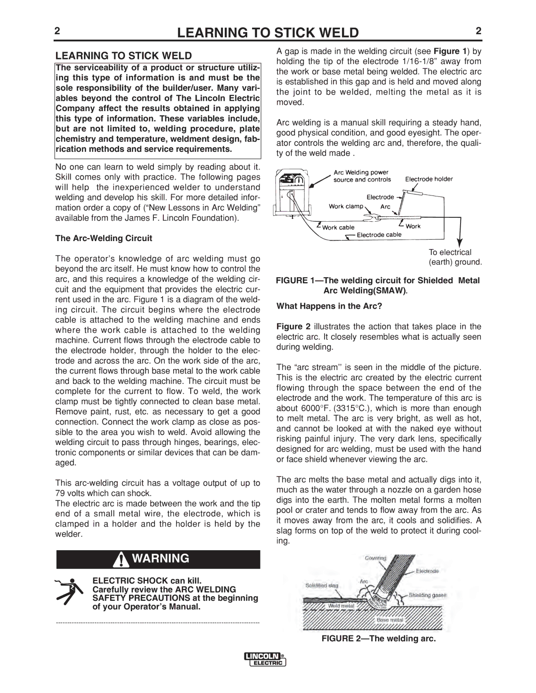
The operator’s knowledge of arc welding must go beyond the arc itself. He must know how to control the arc, and this requires a knowledge of the welding cir- cuit and the equipment that provides the electric cur- rent used in the arc. Figure 1 is a diagram of the weld- ing circuit. The circuit begins where the electrode cable is attached to the welding machine and ends where the work cable is attached to the welding machine. Current flows through the electrode cable to the electrode holder, through the holder to the elec- trode and across the arc. On the work side of the arc, the current flows through base metal to the work cable and back to the welding machine. The circuit must be complete for the current to flow. To weld, the work clamp must be tightly connected to clean base metal. Remove paint, rust, etc. as necessary to get a good connection. Connect the work clamp as close as pos- sible to the area you wish to weld. Avoid allowing the welding circuit to pass through hinges, bearings, elec- tronic components or similar devices that can be dam- aged.
This
The electric arc is made between the work and the tip end of a small metal wire, the electrode, which is clamped in a holder and the holder is held by the welder.
![]()
![]() WARNING
WARNING
ELECTRIC SHOCK can kill. Carefully review the ARC WELDING SAFETY PRECAUTIONS at the beginning of your Operator’s Manual.
A gap is made in the welding circuit (see Figure 1) by holding the tip of the electrode
Arc welding is a manual skill requiring a steady hand, good physical condition, and good eyesight. The oper- ator controls the welding arc and, therefore, the quali- ty of the weld made .
To electrical (earth) ground.